The light produced by the screen does not disappear immediately when bombardment by electron ceases, i.e., when the signal becomes zero. The time period for which the trace remains on the screen after the signal becomes zero is known as persistence. The persistence may be as short as a few microseconds, or as long as tens of seconds or even minutes.
Medium persistence traces are mostly used for general purpose applications.
Long persistence traces are used in the study of transients. Long persistence helps in the study of transients since the trace is still seen on the screen after the transient has disappeared.
Short persistence is needed for extremely high speed phenomena.
The screen is coated with fluorescent material called phosphor which emits light when bombarded by electrons. There are various phosphors available which differ in color, persistence and efficiency.
One of the common phosphor is willemite, which is zinc, orthosilicate, ZnO+SiO2, with traces of manganese. This produces the familiar greenish trace. Other useful screen materials include compounds of zinc, cadmium, magnesium and silicon.
The kinetic energy of the electron beam is converted into both light and heat energy when it hits the screen. The heat so produced gives rise in phosphor burn which is damaging and sometimes destructive. This degrades the light output of phosphor and sometimes may cause complete phosphor destruction. Thus the phosphor must have high burn resistance to avoid accidental damage.
Similarly the phosphor screen is provided with an aluminum layer called aluminizing the cathode ray tube. This is shown in image below.
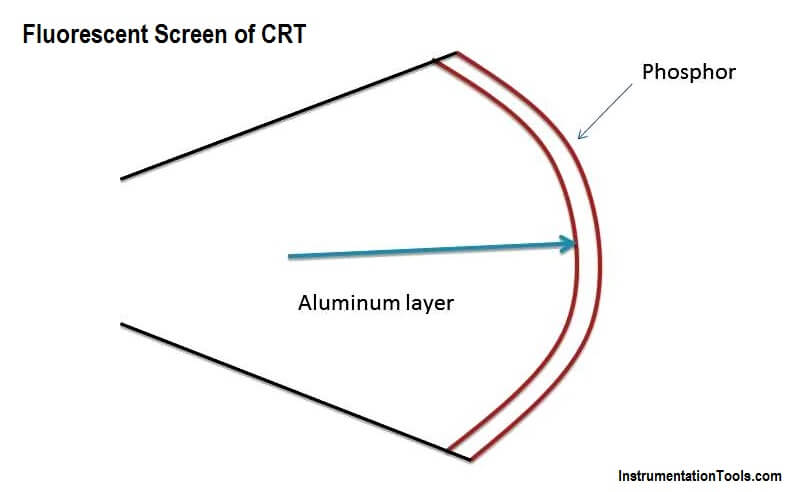
These Aluminizing layers serve three functions:
- To avoid buildup of charges on the phosphor which tend to slow down the electrons and limits the brightness.
- It serves as a light scatter. When the beam strikes the phosphor with aluminized layer, the light emitted back into the tube is reflected back towards the viewer which increases the brightness.
- The aluminum layer acts as a heat sink for the phosphor and thus reduces the chances of the phosphor burning.
Phosphor screen characteristics
- Many phosphor materials having different excitation times and colors as well as different phosphorescence times are available.
- The type P1, P2, P11 or P31 are the short persistence phosphors and are used for the general purpose oscilloscopes.
- Medical oscilloscopes require longer phosphor decay and hence phosphors like P7 and P39 are preferred for such applications
- Very slow displays like radar require long persistence phosphor to maintain sufficient flicker free picture. Such phosphors are P19, P26 and P33.
- The phosphors P19, P26, P33 have low burn resistance. The phosphors P1, P2, P4, P7, P11 have medium burn resistance while P15,P31 have high burn resistance.
Why P31 is commonly used?
Out of these varieties, the materials P31 is used commonly for general purpose oscilloscopes due to following characteristics:
- It gives color to which human eye response is maximum.
- It gives short persistence required to avoid multiple image display.
- It has high burn resistance to avoid the accidental damage.
- Its illumination level is high.
- It provides high writing speed.
Note: the light output of a fluorescent screen is proportional to the number of bombarding electrons, i.e., to the beam current.


Information was so helpful