Wonderware InTouch is famous SCADA software used to visualize and control the processes by using an animated design like a plant layout.
Create Project in Wonderware Intouch
In this article, we will learn to create a new project with an example in Wonderware InTouch SCADA software. Let’s follow the below steps.
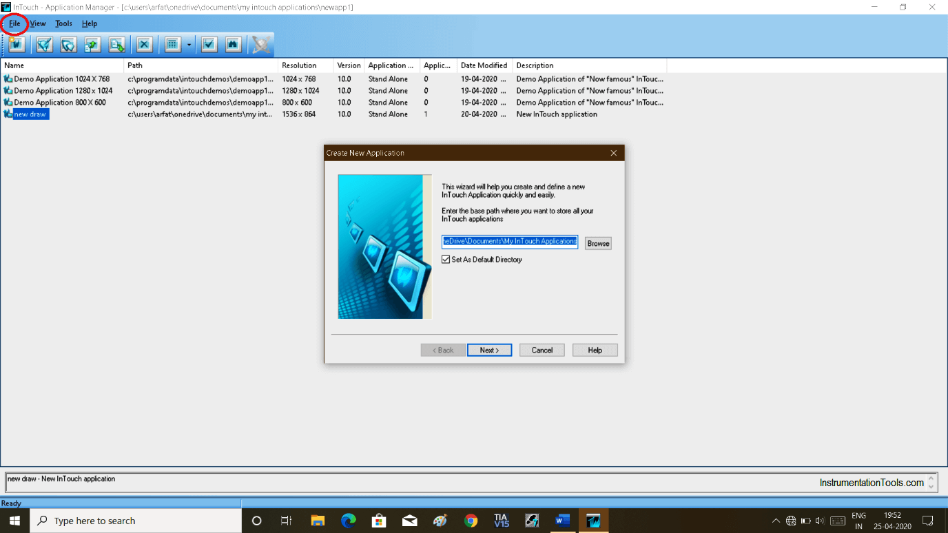
Step 1:
Open InTouch. Click on “file” and select “new”. Following window will pop-up. Click “next” to proceed.
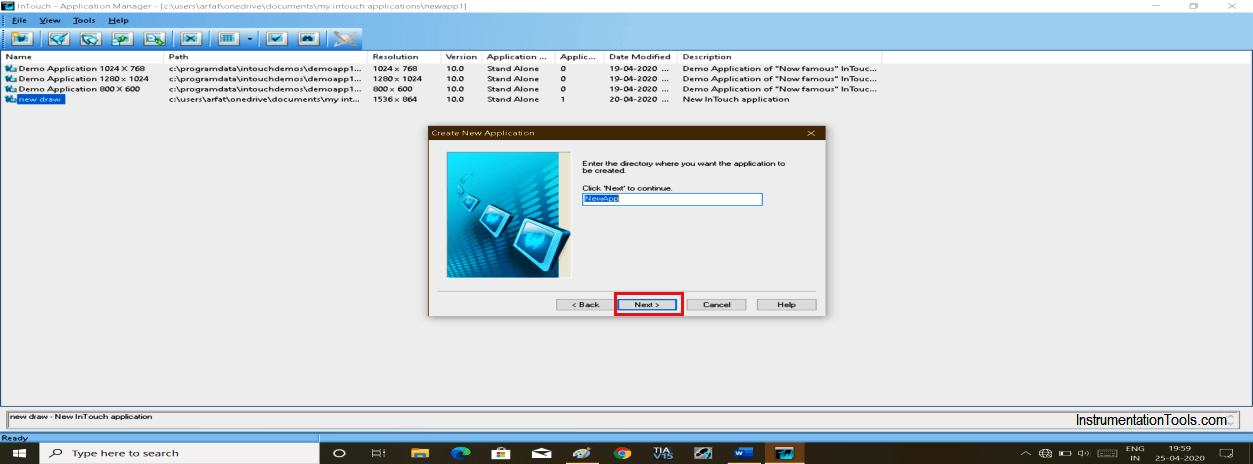
Step 2:
Clicking next will pop-up another window. Here, give a name and click “next”.
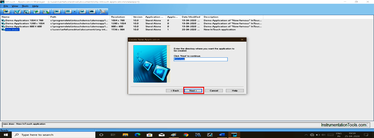
Step 3:
Again another pop-up will open. Give name here too and click “finish”.
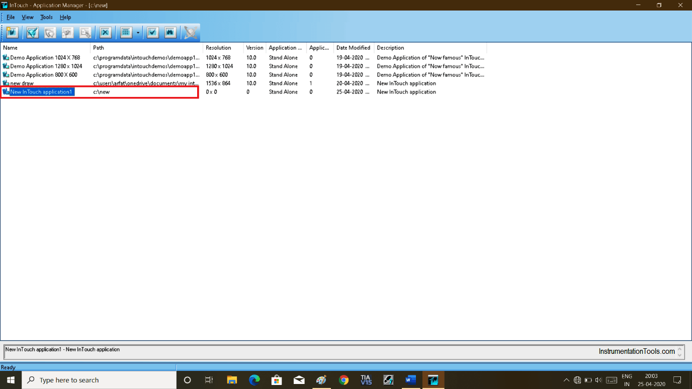
Step 4:
The created project name will be added as shown in the below window.
Double click on it. If it asks for the license the click on ignore to proceed.
Step 5:
The following window will appear as shown below.

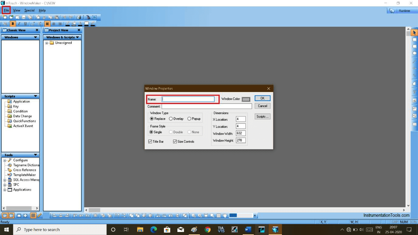
Step 6:
Click on “new” and select “new window” will pop-up a new window.
Again Give a name to this window and hit “ok”.
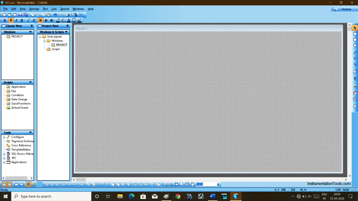
Step 7:
A new window will open as shown in the below figure.
Step 8:
Let’s create a simple program to turn on/off bulb using a logic gate.
To add switch and light click on the “wizard” icon as shown in the below window.
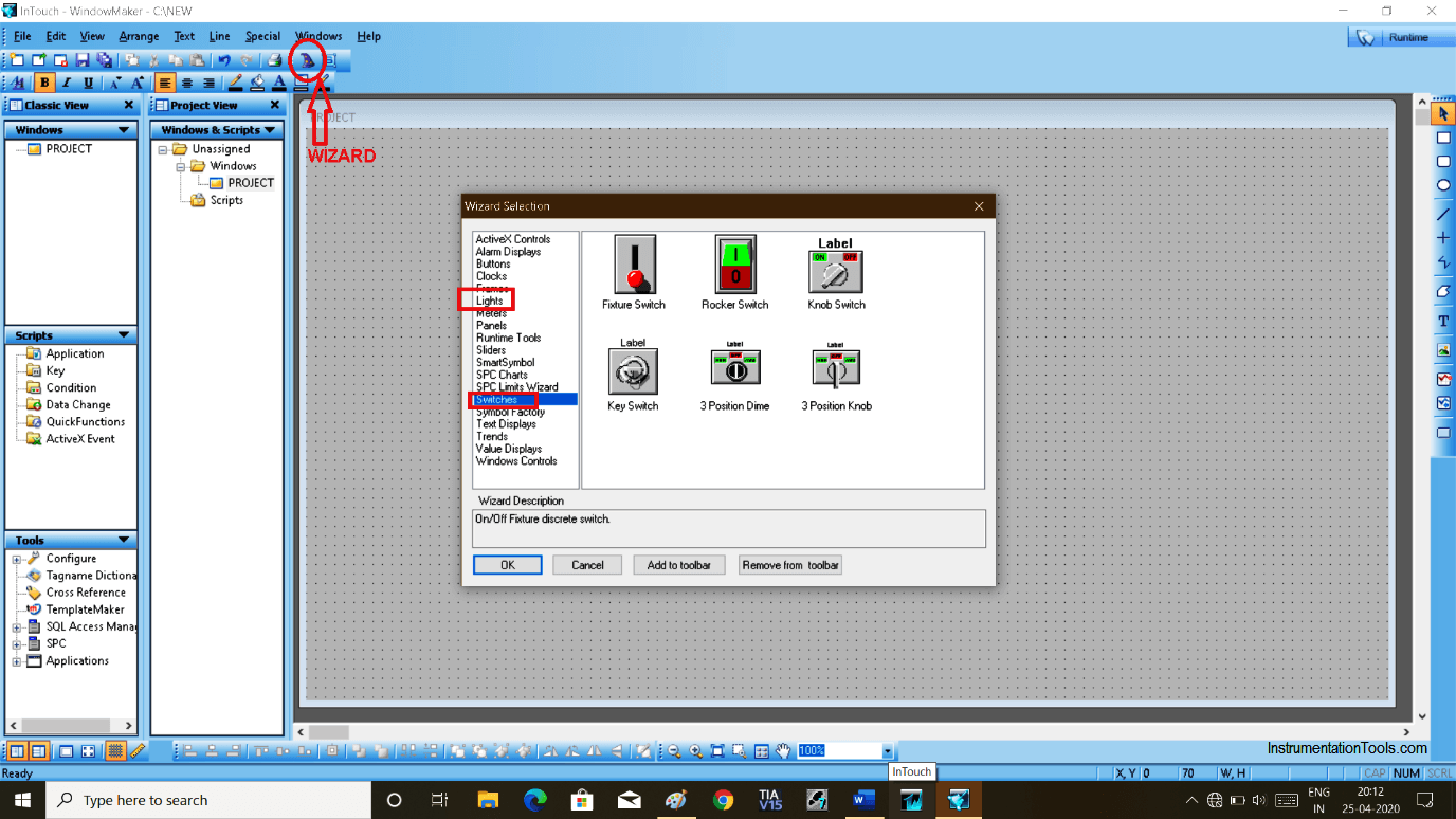
Step 9:
To make AND logic, I have chosen two switches and one light to know the status.
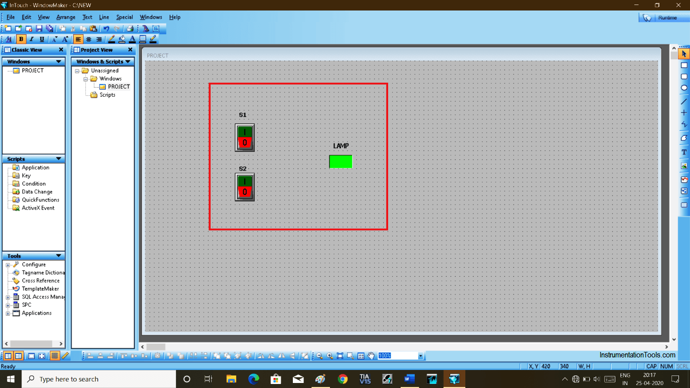
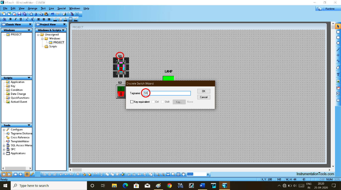
Step 10:
To give tag name, double click on switch and give the name “S1”, same way for the second switch give name “S2”.
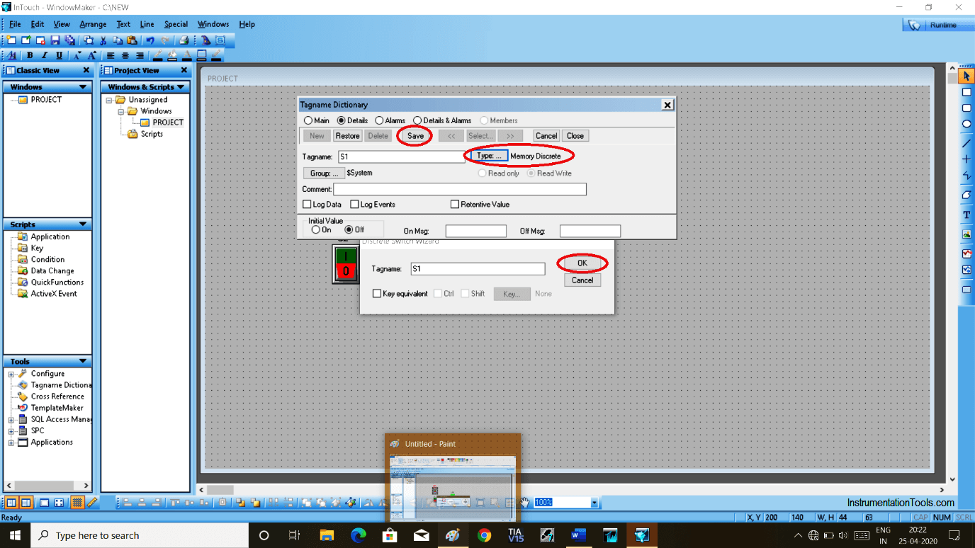
Step 11:
Now When you hit “ok” new pop-up will open as shown in the below window. Select type “memory discrete” and hit “save” to proceed.
We select “memory discrete” because we have a switch (digital) in use.
We are just animating it, we have to select the memory to store the value.
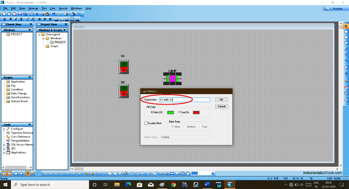
Step 12:
Here, Double click on LAMP, then the pop-up window will open. We are creating AND gate here, so simply we have to write “S1 AND S2” as we have selected name S1, S2 for the switches.
Step 13:
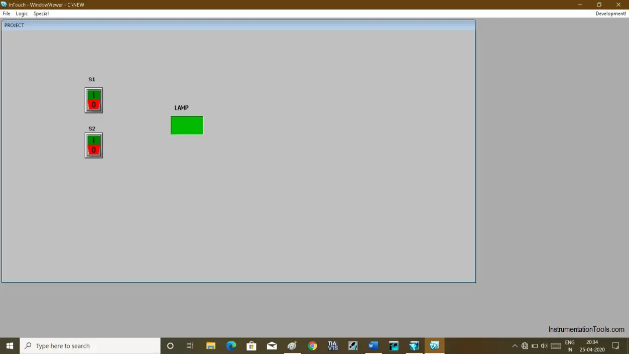
To test the logic, click on “runtime” located on the top right corner as shown in the below window.
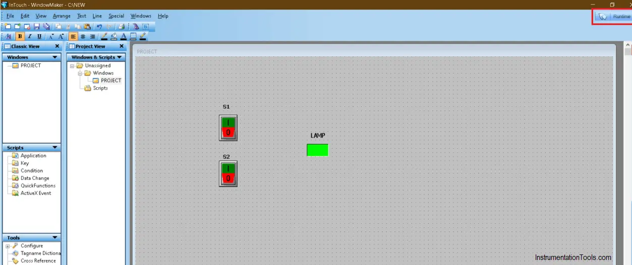
Step 14:
For AND gate, LAMP will only turn “ON” when both switches are “ON”. If you Switch OFF any one input then the output will go OFF.
Author: Suhel Patel
If you liked this article, then please subscribe to our YouTube Channel for PLC and SCADA video tutorials.
You can also follow us on Facebook and Twitter to receive daily updates.
Read Next:
- Troubleshoot PLC Program
- Protect PLC using Password
- Download PLC software
- Siemens PLC Backup
- SCADA Communication


Ver nice content. It’s a helpful topic understanding scada software.