A Closed-Loop Control system can handle a lot of situations in your process or plant.
As this system can maintain a prescribed relationship between the output and the reference input by comparing them and using the difference as a means of control, what are its elements? And how could we use them that is we are going to discuss.
Closed-Loop Control System
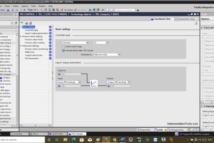
One of the most famous images of a closed control system is the PID controller, this controller can handle and control a process smoothly with high response time and without response overshooting.
But in some cases, there is no need to use the three elements of a PID controller (Proportional – Integral – Differential), in our example we will just use a Proportional controller to control the level of the tank.
A proportional Controller is a basic element in the PID controller you might know that each element in the PID controller has its own function.
For the Proportional controller you can control the response time of your system, as in our example you can control the time taken to fill and discharge of a tank by increasing and decreasing the Proportional Gain as our control signal (which is the out signal) is described by:
C(s) = P e(t)
- C(s): output control signal that handle the process
- P : Proportional gain which is constant
- e(t): error signal which is the difference between set value and process value
What is the Need for a Proportional Controller?
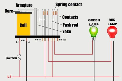
Before we get into our example, we have to understand why we use this type of controlling, why we did not use a simple ON-OFF controlling with the closed loop system.
The answer is the need for Smoothing Control. The ON-OFF control can affect negatively on the stability of the system unlike the proportional controller if the gain is adjusted correctly it will give you smooth and stable performance.
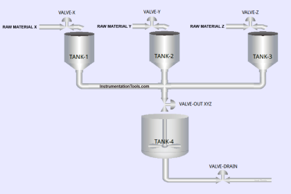
Explaining of the System Components
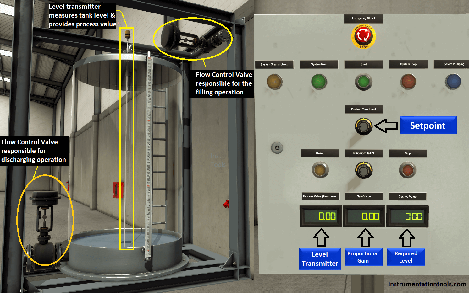
Our example consists of two main components:
Tank
Level Transmitter that provides our system with the real process value.
Flow control valve for controlling the filling operation, controlled by an analog output (0:10 V)
Flow control valve that controls discharging process, controlled by an analog output (0:10 V)
Control Panel
Start & Stop Push Buttons to control the starting and stopping of the operation
Variable Potentiometer to enter the SET value (desired tank level)
Variable Potentiometer to enter the suitable value for the Proportional Gain
LCDs to display some of the system values
Emergency Stop & Lambs for some system indications
Process Explaining
So after we have discussed the process components here we are to explain the steps to start the process.
First of all we will begin our process by pressing on the start push button, then we have to set our desired value using the potentiometer.
However, the system indicates an error signal (there would be a difference between the set value and the process value) the filling valve will not open till that you will adjust the Gain to be more than Zero.
Here the system will start with the filling operation till the process value reaches the set value, and also we will notice that the filling valve, in the beginning, opens with 100% till the process value become closer to the set value then the filling valve will start to close slowly to handle the desired level smoothly and without any overshooting, and it is the same for discharging of the tank.
NOTE you can speed your system response by increasing the Proportional gain but on the other hand, you might have some response overshooting which could affect negatively the stability of your system, so whenever you are selecting a value for the Proportional gain be careful to not increase that value so much just put it in a suitable range.
Controlling Tank Level
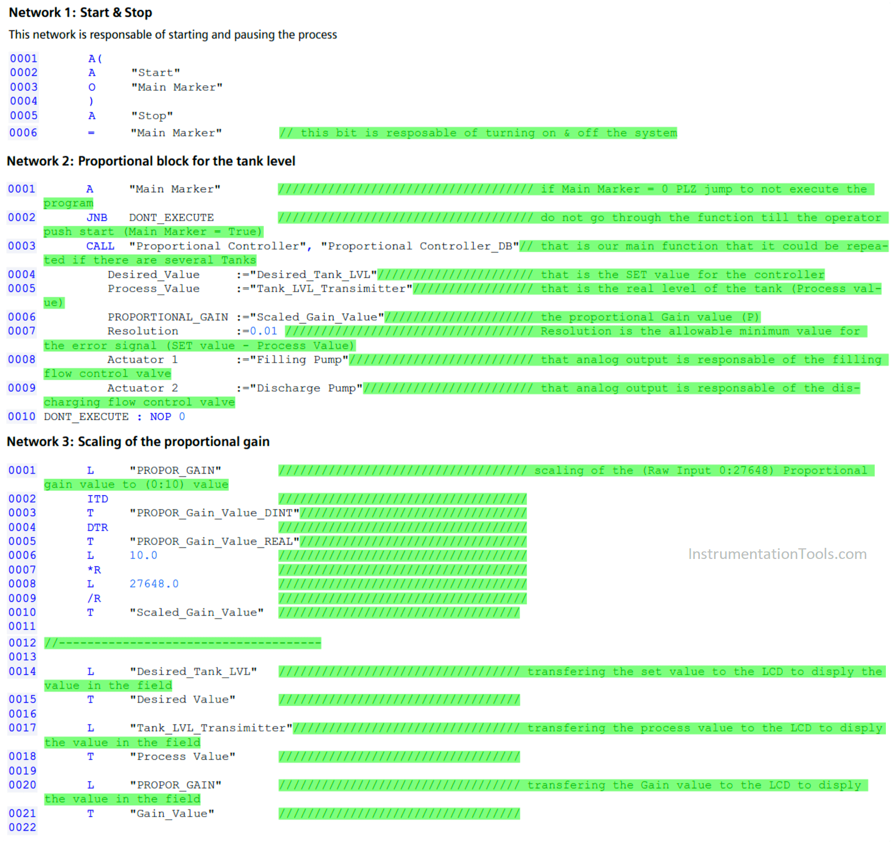
Here for the coding, we are using STL language and now we will explain each network in the code:
To download the PLC STL program: Click Here
Network 1:
Here we are using a memory bit to control the starting and stopping of the process
Network 2:
Here for the first and second line, it is the bit that is used in the first network “Main Marker” if that bit is TRUE the scan cycle will get into the Tank Block and it will execute the program and if the Main Marker is FALSE the scan cycle would ignore this routine and it will jump to DONT_EXECUTE label.
Network 3:
Here we are conditioning the RAW input of the proportional gain value from (0 : 27648) to be scaled to (0 : 10)
Here we are moving the input values of the process (Set value – Process value – Gain value) to be displayed on the LCDs in the field
Coding for the Function Block
For proportional controller program: Click Here
Network 1:
- Scaling of the desired value to be (0:300) cm
- Scaling of the process value to be (0:300) cm
Network 2: Getting the desired and process values in our block to be processed
Network 3: Getting the error signal
Error signal = set value – process value
Network 4: Creating Proportional Terminal
Network 5: Here we are generating the Control Signal by multiplying the Gain with the error signal
Control Signal = Proportional Gain * Error Signal
Network 6: Conditioning of Analog outputs
Scaling of the analog output signal from (0:3000) to be (0:27648)
Network 7: Filling Operation
Network 8: ShutDown Filling and Draining Valve
Network 9: Draining Operation
Simulation Video
See the below video to Learn the controlling of tank level using the proportional controller and the impact of gain in the siemens Tia portal with simulation.
If you liked this article, then please subscribe to our YouTube Channel for PLC and SCADA video tutorials.
You can also follow us on Facebook and Twitter to receive daily updates.
Read Next:


Very good tutorials.