A control valve is the most commonly used to regulate fluid flow in the process.
The international society of automation defines the control valve as a power-operated device that operates a fluid flow rate in a process control system.
Control Valve Accessories
The following list shows the most commonly used accessories with the control valve, as per the requirements.
- Pneumatic Positioners
- I/P Transducers
- Volume Boosters
- Position Transmitters
- Limit Switches
- Solenoid Valves
- Air Lock relay
- Handwheel
If a control valve is equipped with proper accessories can become more useful for process control also provide smooth and efficient operation. Pneumatic control valve accessories help ensure optimal performance and are an essential component in a process control system.
Purpose of Control Valve Accessories
There are five basic reasons that accessories are added to a control valve:
- Improve process control
- Improve safety for the process or personnel
- Improve valve performance or speed of response
- Monitor or verify the valve responsiveness
- Diagnose potential valve issues
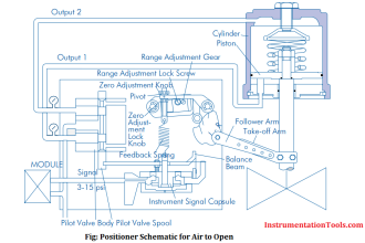
Advantages of Valve Positioner Includes
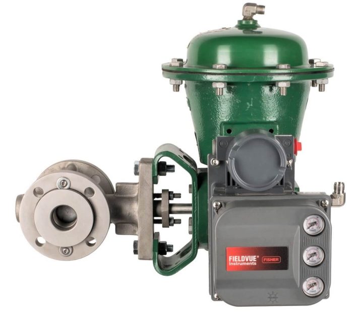
Image Credits: Fisher
- Minimizing the effect of friction, hysteresis, and dead band on the valve stem.
- Enables signal range change.
- Allows control valve signal reversal: A positioner can operate in either direct or reverse acting mode. In direct acting mode, an increase in control signal pressure causes an increase in positioner output air pressure. In reverse acting mode, an increase in control valve signal pressure causes a decrease in positioner output air pressure
- A positioner Increases the speed of response of the actuator.
- Allows valve flow characteristics to be changed.
- Allows split range operation. In a split range control loop, one controller output is used to drive two control valves.
I/P Transducer
An current to pressure uses a converter module that converts a 4 to 20 mA current input to a proportional 3 to 15 psi pressure output.
In some applications, where a high level of positioning accuracy by a positioner is not required. In these applications, an electro-pneumatic (I/P) transducer only can be used.
Read: I/P Converter Principle
Volume Boosters
When the actuator volume is very large, the control valve positioning speed of response becomes less.
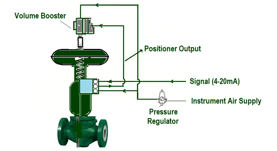
Volume boosters are used to provide additional pneumatic thrust output capacity to a valve assembly.
Single-acting actuators typically use one volume booster. Double-acting actuators require at least two volume boosters.
Read: Volume Booster Principle
Position Transmitter
The purpose of a position transmitter is to provide independent, separate valve position feedback to the control system. Position feedback of the control valve often becomes necessary as it is used for process monitoring, troubleshooting, or startup/shutdown verification from the control room by an operator.
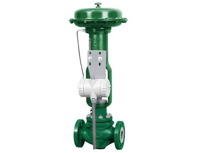
Image Credits: Emerson
The position transmitter is mounted directly to the valve yoke and measures the position of the valve stem or shaft.
Read: Positioner Principle
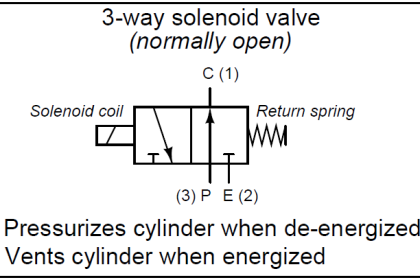
Solenoid Valve
In some applications, the solenoid valve will trap air in the actuator to lock the valve in its current position.
In some applications, the solenoid valve will vent out the air from the actuator to allow the valve to move to its no air position.
Read: 2 way Solenoid Valve
Limit Switches
The purpose of a limit switch is to provide a discrete open or discrete close input signal to the control system when the valve reaches a specific position within its range of travel.
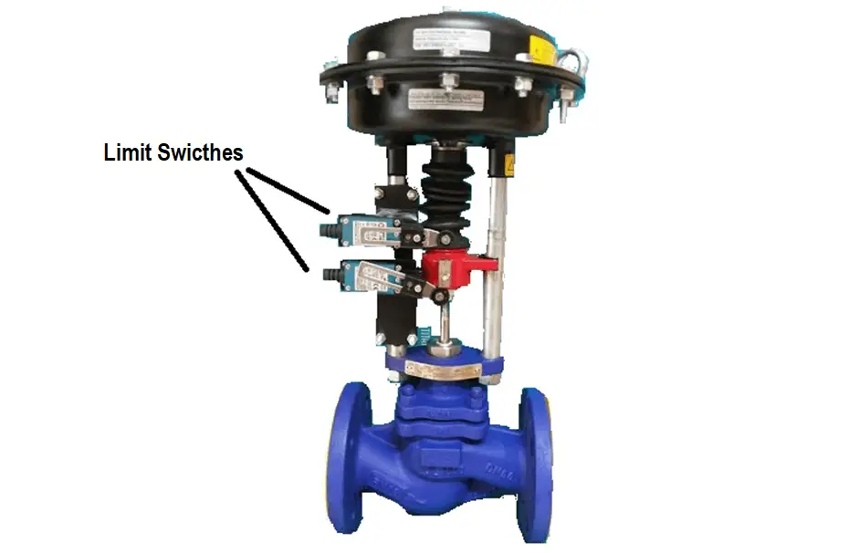
Image Credits: Titanindustech
Limit switches, which are mounted on the control valve and on the yoke are also used for process monitoring, troubleshooting, or startup/shutdown verification from the control room by an operator.
These switches will only provide specific valve position feedback. These can be mounted on the control valve to get additional feedback signals to the DCS or PLC systems as per our requirement.
Trip Systems – Airlock relay
Trip systems such as air lock relays are used in control applications where a specific actuator action is required in the event that air supply pressure is lost. These are used with double-acting actuators that do not have an inherent air, fail state, or with single or double-acting actuators to provide pneumatic lock-up.
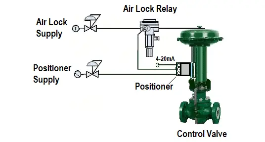
When the instrument air supply pressure falls below the trip point, the trip valve causes the actuator to fail up, lock the control valve in the last position, or fail down.
For double-acting applications, an air volume tank provides the reserve air capacity to operate the valve in case of air supply failure and until the supply pressure is restored. When once the air supply pressure restores, rises above the trip point, the trip valve automatically resets, turns normal, and allowing the system to return to normal operation.
Read: Air Lock Relay Principle
Handwheel
Handwheels for diaphragm actuators of the control valve are often used as adjustable travel stops. They also provide a manual means of positioning the control valve in an emergency.
They are arranged in two ways to a control valve.
- Side-mounted handwheel
- Top-mounted handwheel
- A Side-mounted handwheel at the control valve can be used to open or close the valve in any direction at any point in the actuator stem travel.
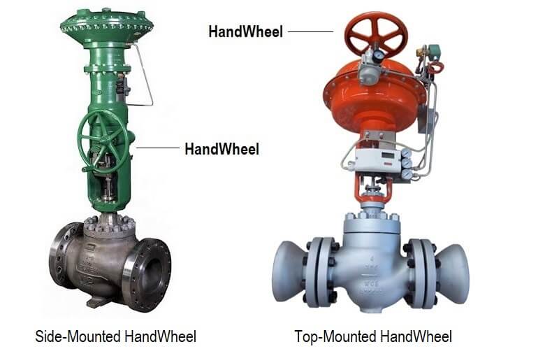
The side-mounted handwheel can be placed to limit travel in any direction, but not both directions at the same time. By keeping the handwheel of the control valve in the neutral position, automatic operation is possible throughout full valve travel.
Top-mounted handwheels are used for “infrequent service” to manually stroke the valve.
Read Next:
- Failures in Control Valves
- Control Valves Checklist
- Relation between Cv and Kv
- Air Consumption Calculation
- Choose a Control Valve