Are you an Control and Instrumentation Engineer ? Recently joined as a Fresher or Trainee engineer in the Instrumentation department? then this article helps you to get an overall outlook of Instrumentation including field instruments and control systems.
This guide provides you the index of industrial instrumentation. As a trainee engineer, the first and most important thing is to know the list of topics to learn and study the instrumentation subject.
Control and Instrumentation Engineer Study Guide

Note : Click on the image to Zoom
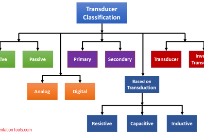
The above image shows the detailed classification of control and instrumentation engineering.
You can find the respective topic links in the below list.
-
Programmable Logic Controllers (PLC)
-
Distributed Control Systems (DCS)
-
Safety Instrumented Systems (SIS)
-
Flow Measuring Devices
-
Level Measuring Devices
-
Temperature Measuring Devices
-
Pressure Measuring Devices
-
Vibration Measuring Devices
-
Fire and Gas Detectors
-
Control valves
-
Analyzers
-
Switches
Do you have any technical queries on the above topics ? No need to worry !!! You can ask instrumentation experts at Instrumentation Forum. Click Here.
The below list shows the different types of instrumentation engineers documents which are useful during construction, erection, pre-commissioning, commissioning and maintenance activities. Some documents list may vary as per industry type like oil and gas, cement plant, power plant, pharmacy etc.
Also Read: Instrumentation Design
Study about these documents also.
Instrument Specifications
- Gas/Condensate/Oil Metering Specification
- Automation System Network Spec
- Control Panel, Cabinet and Rack Specification
- Control Valve Specification
- Fusible Plug Panel Specification
- General Instrument Design
- HSSD Specification
- Instrument / Telecom cable Specification
- Instrumentation & Control Section of The Basis of Design
- MCS, PSD, & ESD System Specification
- Specification for Pressure Safety and Relief Valves
- Specification for Shutdown Valves & Blowdown Valves and Actuator Assemblies
- Typical System Functional Design Spec.
- Wellhead Control Panel Specification
Instrument Philosophies
- Automation System Philosophy
- Automation System Reset & Override Philosophy
- Fire and Gas Detection Philosophy
- Instrument Earthing Philosophy
- Shutdown Philosophy
Documents Related To Automation System
- Fire & Gas Cause / ESD and Effect Chart
- Serial Link Data Listings and Addresses – Allocation Gas Meter, Chemical Injection, Wet Gas Meter, Fire Water Pump, Glycol Reboiler, MV SWGR, Fire Water Pump
- Graphic for F&G, MCS, PSD/ESD (Review)
- Instrument Cable Block Diagram-MCS, PSD/ESD, TCS
- Instrument Logic Diagram for Actuated Valve, ESD/PSD, F&G, Pump & Fan Motor, MCS, TCS
- Instrument loop safety integrity level listing (SIL).
- Logic sequence flow step charts.
- Master Alarm & Trip Schedule
- Network Architecture (Review)
- PSD/ESD Cause and Effect Chart
- Serial Link Data Listings and Addresses
- Shutdown Hierarchy (Shutdown flow block diagram identifying each level and causes & effects)
- Instrument I/O List MCS, PSD, ESD, F&G, TCS
- Instrument & Automation Equipment List
Miscellaneous Documents
- Instrument Installation, testing, Pre-Commissioning, and Commissioning
- Instrumentations Tools
- Intruder and CCTV management
- Laboratory Equipment List
- List of Test Equipmets
Instrument Calculations
- Calculation of Actuator sizing.
- Calculation of Control valve sizing and noise.
- Calculation of Flowmeter sizing.
- Calculation of Heat dissipation.
- Calculation of Hydraulic tank, pumps and accumulator sizing calculations.
- Calculation of Instrument power cable sizing calculations.
- Calculation of Instrument utilities consumption.
- Calculation of Relief valve sizing and noise.
- Calculation of Restriction orifice sizing and stress and noise.
- Calculation of Thermowell and other insertion device stress and wake frequency.
- Calculation of Tubing sizing calculations (Hydraulic)
- Calculation of Valve speed calculations (where required)
Instrument Datasheets
- Datasheet of Actuated Ball Valves
- Datasheet of Actuated ON/OFF Valves
- Datasheet of Annubar Flow Meter
- Datasheet of Anti-Surge Control Valve
- Datasheet of Bubble Type Level Transmitters
- Datasheet of Choke Valves
- Datasheet of Control Valves
- Datasheet of Coriolis Flow Meter
- Datasheet of Deluge Valves
- Datasheet of Dew Poin Analyser
- Datasheet of Differential Pressure Indicating Transmitters
- Datasheet of Differential Pressure Indicators
- Datasheet of Displacer Level Transmitters
- Datasheet of Duplex RTD
- Datasheet of Electrical Hand Switches
- Datasheet of Flanged Thermowells
- Datasheet of Flow Meter (Ultrasonic)
- Datasheet of Flow Switch
- Datasheet of Gas Analyzer Chromatograph
- Datasheet of Guide Wave Radar Level Transmitters
- Datasheet of H2 Detectors
- Datasheet of HC Gas Detectors (Open Path)
- Datasheet of HC Gas Detectors (Point)
- Datasheet of Heat Detectors
- Datasheet of Infra Red Flame Detectors
- Datasheet of Intruder Detectors
- Datasheet of Junior/Senior Flow Elements
- Datasheet of Magnetic Flow Meter
- Datasheet of Magnetic Level Gauge
- Datasheet of Magnetostrictive Level Transmitters
- Datasheet of Moisture Analyser
- Datasheet of Orifice Flow Element
- Datasheet of Pig Indicators
- Datasheet of Pig Signaller – Intrusive
- Datasheet of Pneumatic Pressure Pilot
- Datasheet of Pressure Indicating Transmitters
- Datasheet of Pressure Indicator
- Datasheet of Pressure Regulator Valves
- Datasheet of Pressure Safety/Relief Valves
- Datasheet of Pressure Switch
- Datasheet of Restriction Orifices
- Datasheet of Rotameter
- Datasheet of Rotameter with transmitter
- Datasheet of Self Acting Regulator Valves
- Datasheet of Smoke Detectors
- Datasheet of Temperature Indicators & Thermowells (Bi-Metal)
- Datasheet of Temperature Transmitters & Thermowells
- Datasheet of Temperature Indicating Transmitters & Thermowells
- Datasheet of Wet Gas Meter
Instrument Layout & Drawings Inside CCR/EER
- Central Control Room Instrument Equipment Layout
- Central Control Room Earthing Layout
- Earthing Layout – Central Control Room
- EER Earthing Layout
- Electrical equipment Room Instrument Equipment Layout
- Fire & Gas & ESD display panels layouts in CCR (Review)
- Instrument Air Sub Header Layout – Each Deck and Platform
- Instrument CCR/Accomodation MCT Interface Layout
- Instrument/Telecom MCT Layout – CCR and EER
- Single line diagram for instrument power supplies in CCR
Instrument Drawings
- Instrument Grounding Layout – Each Deck and Platform
- Instrument Level Sketches
- Instrument Location Plan – Each Deck and Platform including CCR and EER
- Instrument Mounting Details
- Instrument Pneumatic Hook-up
- Instrument Process Hook-up Drawings
- Instrument Tubing Hydraulic Routing
- Instrument Tubing Pneumatic Routing
- Instrument/Telecom Cable Routing
- Instrument/Telecom Cable Tray Layout
Instrument Material Take Off
- MTO – Cable Glands
- MTO – Earthing Devices
- MTO – Fusible Plugs
- MTO – Installation Support
- MTO – Instrument & Telecom Cable
- MTO – Instrument Cable & Tubing Tray
- MTO – Instrument Cable Accessories
- MTO – Instrument Cable Ladder & Tubing Tray
- MTO – Instrument Distribution Manifold
- MTO – Instrument Fittings
- MTO – Instrument Junction Box
- MTO – Instrument Manual Valves
- MTO – Instrument Tubing
- MTO – Multiple Cable Transit (MCT)
Instrument Schedules
- Instrument Cables Schedule
- Instrument Index


I really appreciate this website it gives a lot of help to engineers. I am hopping for adding more knowledge about instruments.
This is the most important topic that I saw from others that they sent.so pls sent this full of listed topics with the full description with it daigram.
Thanks in advance
Tubing Schedules not added
Please include the Gland box design and installation details.Many clients are using Gland boxes for the cellar area of the buildings instead of Multi cable transit.
I really appreciate this site for the knowledge and help being shared here. Thanks alot..