In this post, we will see the working of a contactor, wiring and terminals, and connection between the contactor and a PLC system.
A contactor is a device that is used to control the supply of a three-phase power supply in an electrical circuit.
The contactor’s role is to switch on or off the power supply to its connected output load.
Connection between PLC and Contactor
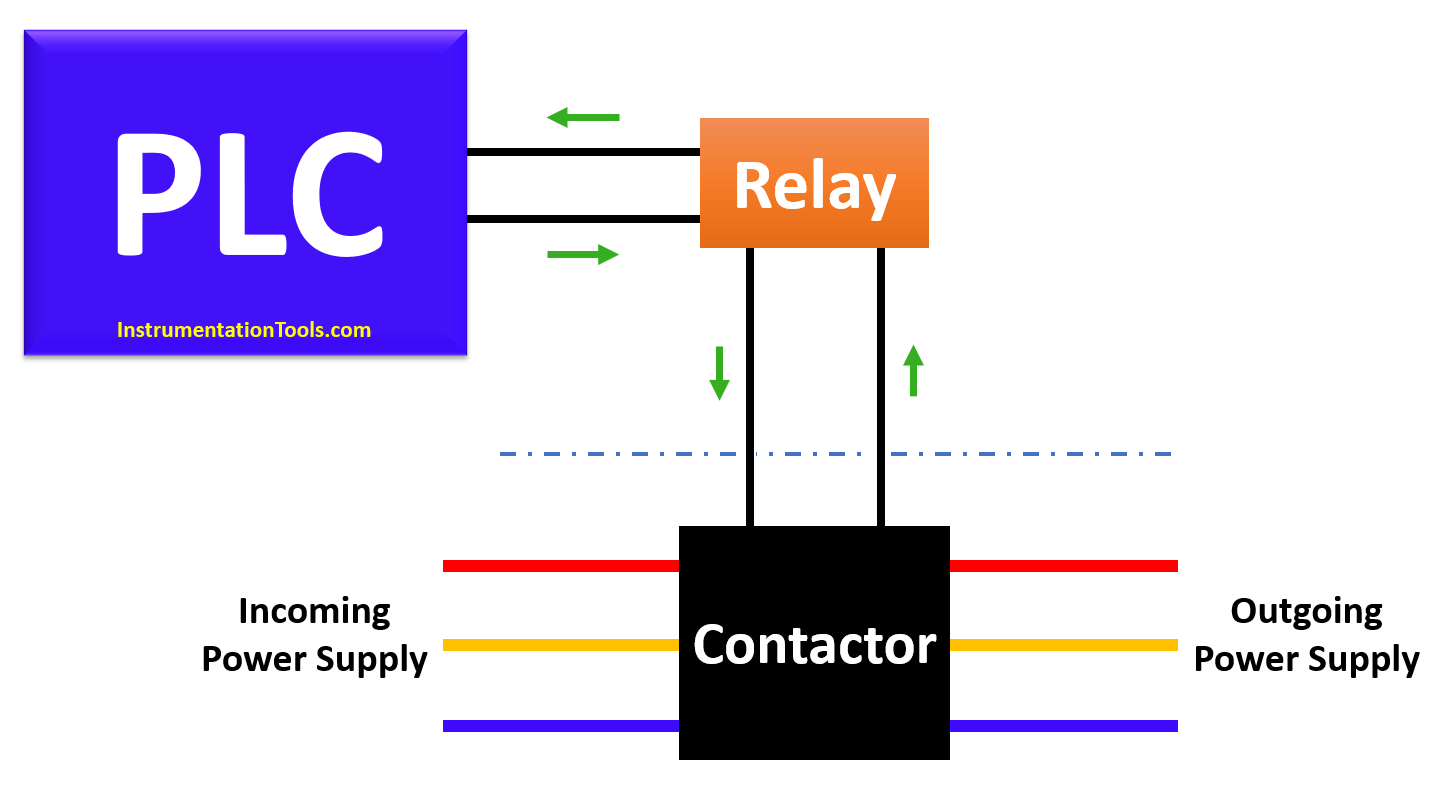
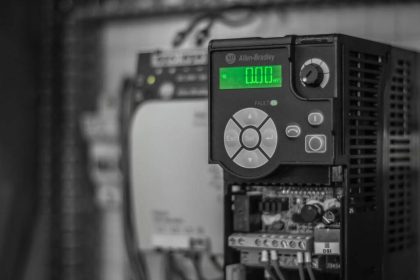
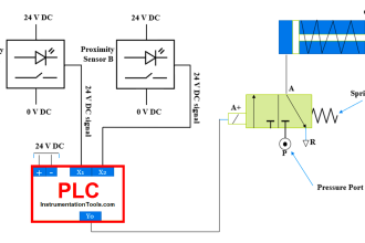
As seen in the image above, the contactor has three connections – a three-phase power supply, a contact for energizing it, and a contact for giving feedback to the PLC.
The image shown describes the generally used setup for connecting a contactor to the PLC or relay.
Working of Contactor
Let us understand the working of a contactor. When the PLC digital output turns on, the relay is energized.
The output contact (NO) of the relay becomes closed and passes a supply potential connected through its common terminal to the NO contact and then to the contactor pin.
This energizes the contactor and switches on the three-phase supply connected at its input terminal to its output terminal. The contactor then passes its running feedback back to the PLC through an auxiliary contact connected to it.
Due to this setup, three-phase equipment (for example a motor) gets controlled by a PLC in a safe manner.
Video: PLC and Pump Control
Relay Versus Contactor
Many people ask whether they can directly connect a relay to the motor; as a relay too is a contact device. It should not be done, as the voltage and current ratings of a relay are very small as compared to a contactor.
A relay cannot handle a large load like a motor and also, there are very few relay devices available in the market which has a three-phase connection in it.
Contactor Terminals and Wiring
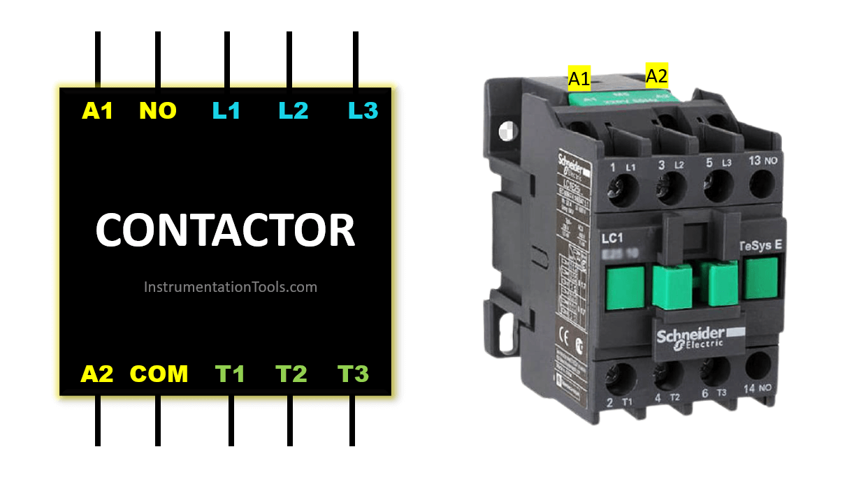
Refer to the above image to understand its wiring. A1 and A2 are energizing contacts.
There are DC and AC options available in it. NO/NC and COM are the auxiliary contacts that get energized depending on the switching of the contactor.
L1, L2, and L3 are the input three-phase terminals. T1, T2, and T3 are the output three-phase terminals. L1 is switched to T1, L2 is switched to T2, and L3 is switched to T3 when the contactor is turned ON.
In some circuits, an overload relay is connected after the connector. It monitors the overcurrent of the motor and trips the circuit in case of a short circuit or over current. Its use depends on the application.
This is the working of a contactor. Basically, it is used for switching purposes and to control heavy and high voltage devices.
If you liked this article, then please subscribe to our YouTube Channel for Instrumentation, Electrical, PLC, and SCADA video tutorials.
You can also follow us on Facebook and Twitter to receive daily updates.
Read Next:
- Interposing Relay Panel
- Intelligent Motor Control Center
- Motors and Alternators Quiz
- Mitsubishi PLC Training Course
- What is a Safety Relay?