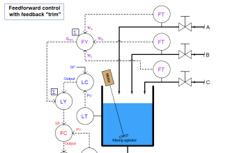
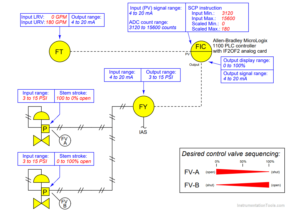
Suppose you are asked to configure the instruments in this flow control loop to sense and display process flow over a range of 0 to 180 gallons per minute (GPM), with the loop controller actuating two split-ranged control valves in a complementary sequence.
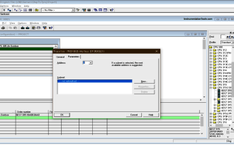
A “Scale-with-Parameters” (SCP) instruction programmed into the Allen-Bradley controller is supposed to take the analog-to-digital converter’s raw count value as an input and scale it into units of GPM for the operator to read on a display:
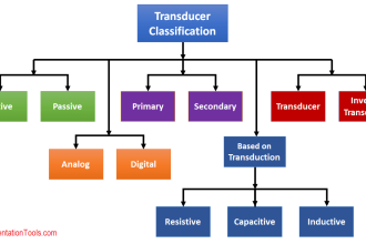
Configure the Instruments
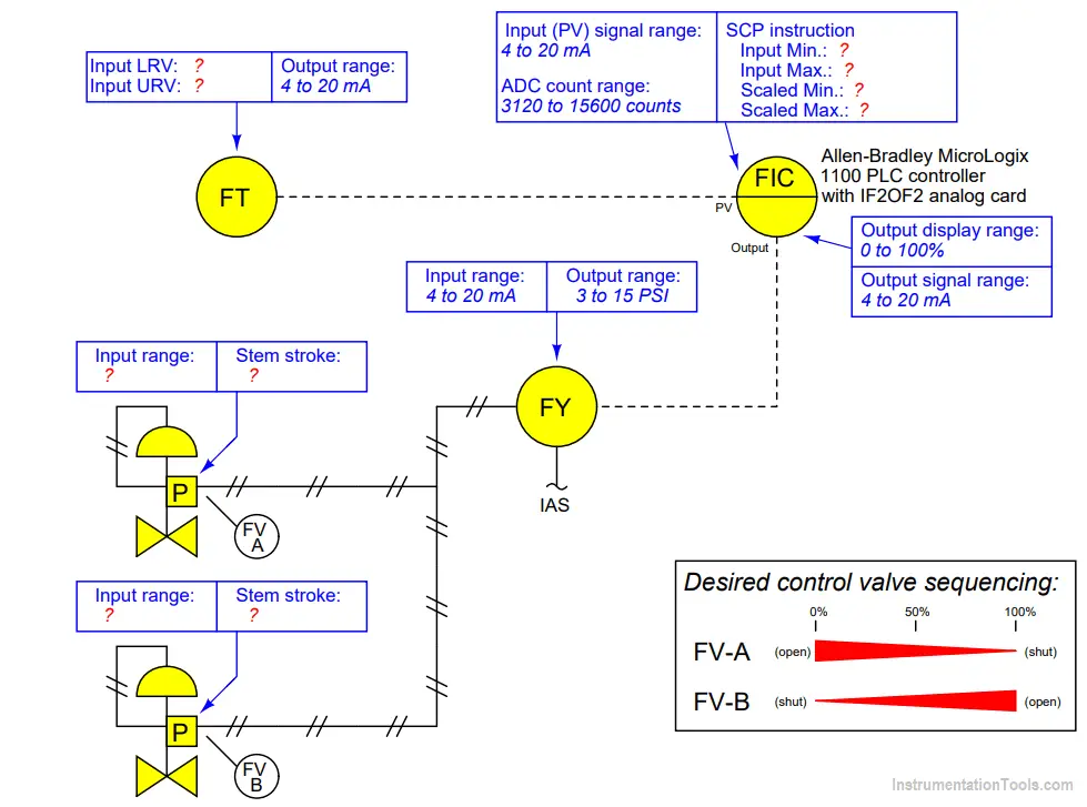
Write the proper range values inside the boxes near each instrument, showing the proper configuration for each instrument needed to achieve the desired result.
Suppose the controller displayed a flow of 129 GPM when the actual process flow was 135 GPM. First, identify two possible locations in this loop for a calibration error that would account for this discrepancy. Then, assuming only one fault, explain how you could positively determine the location of this calibration error with a single diagnostic test.
Suppose valve FV-A was 41% open and FV-B was 59% open when the controller output displayed 50%. First, identify two possible locations in this loop for a calibration error that would account for this discrepancy. Then, assuming only one fault, explain how you could positively determine the location of this calibration error with a single diagnostic test.
Flow Control Loop
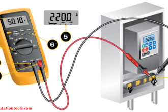
A PV measurement error could lie within the transmitter, or within the controller’s analog input. A single current measurement of the transmitter’s signal will tell you where the calibration error resides.
A valve positioning error affecting both control valves could lie within the I/P transducer or within the controller’s analog output. A single current measurement of the controller’s output signal will tell you where the calibration error resides.
If you liked this article, then please subscribe to our YouTube Channel for Instrumentation, Electrical, PLC, and SCADA video tutorials.
You can also follow us on Facebook and Twitter to receive daily updates.
Read Next:
- Smart Transmitter Range
- Field Instrument Errors
- Process Control Loop
- Failures in Control Valve
- Split Range Control Loop