Learn the concept of the Shift Register instruction and examples of its use in CX-Programmer Omron PLC programming.
The Concept of Shift Register
SFT(010) instruction is a Shift Register and it is one of the instructions used in PLC (Programmable Logic Controller) programming to shift the values in a register sequentially. The shift register instruction is generally used for those operations that require temporary data storage or to process data sequentially.
SFT(010) Instruction
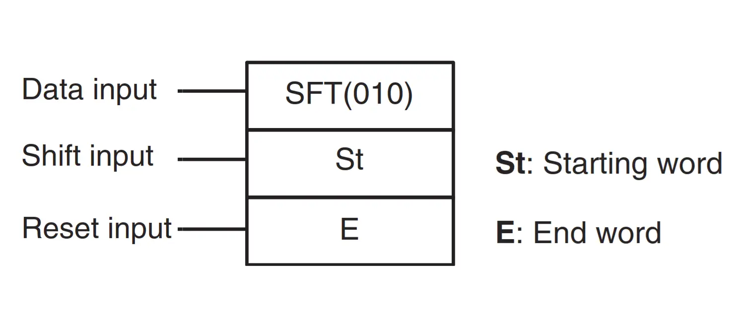
The SFT(010) instruction has 3 Input parameters and 2 Word Memory parameters. That is;
- Data Input: The “Data Input” serves to set the condition of the data to be executed, the condition in question is “True / 1” or “False / 0”.
- Shit Input: This is a parameter that serves to execute the data condition of Bit memory.
- Reset Input: It serves to reset the condition of all Bits that have been executed to the “False/0” condition. When the reset input is ON, all bits in the register slide from the rightmost designated word (St) to the leftmost designated word (E) will be reset to the “False/0” state. Reset inputs take priority over other inputs.
- St/Starting Word: The initial address parameter of the Word Memory to be executed.
- E/End: The expiration parameter of the executed Word Memory address.
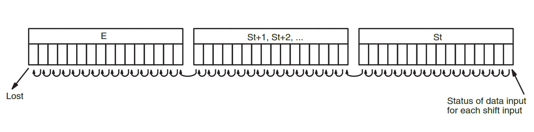
In the figure above, when the execution condition on the input shift changes from OFF to ON, all data from “St” to “E” is shifted to the left by one bit (from the rightmost bit to the leftmost bit), and the ON/OFF status of the input data is placed on the slightly rightmost.
Watch the below video to understand the Omron shift registers.
Omron CX Programmer Shift Register
Using SFT(010) instructions in organizing and processing data can be done sequentially in an automation system. One of the uses of SFT(010) instructions in CX-Programmer is, suppose there is a Conveyor Belt that carries goods from one point to another in an automation system.
Each item may have certain information that needs to be processed. You can use the Shift Register to store this information temporarily while the goods (products) move through the Conveyor Belt.
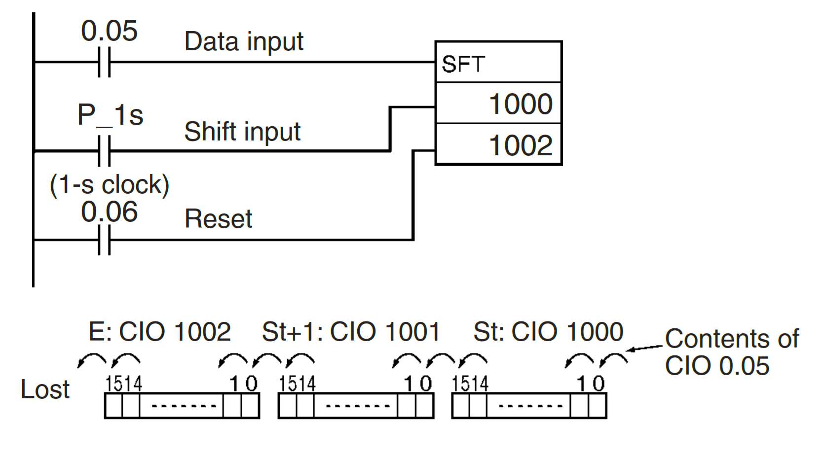
The example above shows a 48-bit sliding register (3 Word Memory) using the Word Memory allocation of CIO 1000 to CIO 1002.
A clock pulse of 1 second (P_1s) is used so that the execution condition generated by CIO 0.05 is shifted to register 3 Words between CIO 1000.00 and CIO 1002.15 every second (1s).
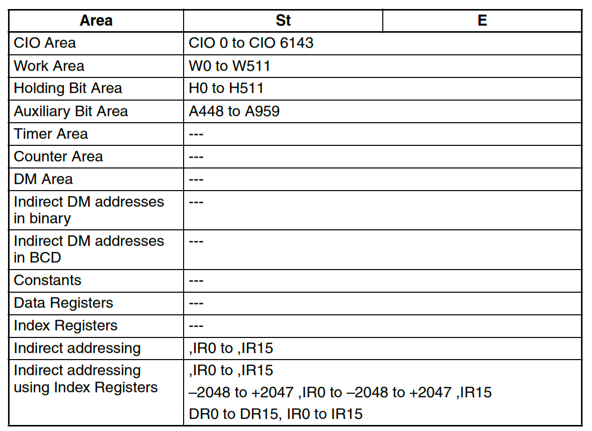
SFT Instruction Usage Memory Allocation Table (010)
Omron PLC Shift Register Program
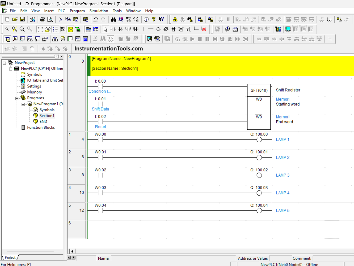
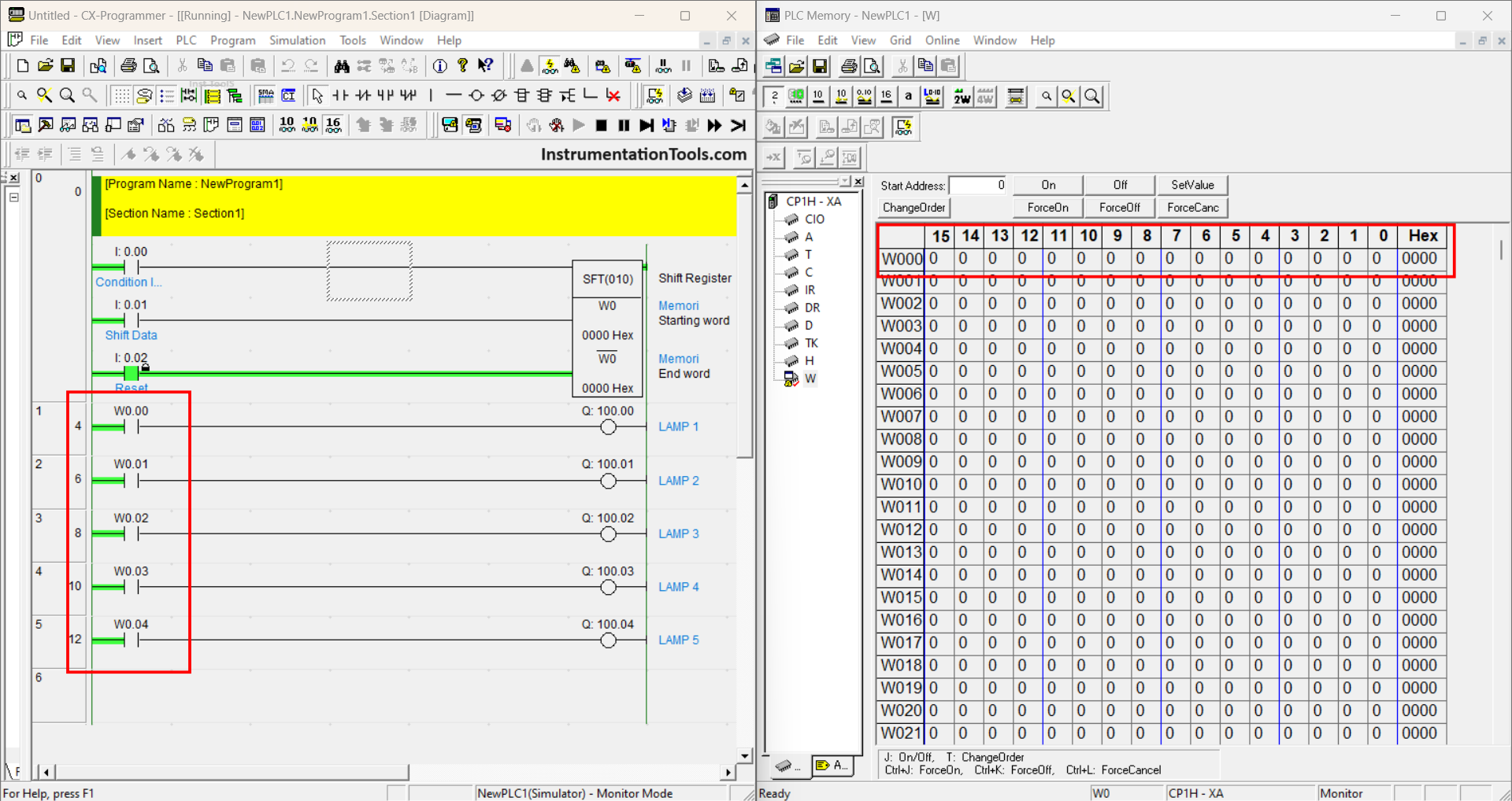
This PLC program consists of 3 CIO contacts, Condition Input (0.00), Shift Data (0.01), and Reset (0.02). The Starting Word parameter starts from the memory address (W0) and the End Word parameter at the address (W0) because the executed data starts and ends at the same address (W0), the Bit address to be executed starts from W0.00-W0.15.
In the program above there is also a NO (Normally Open) contact that has an address W0.00-W0.04 and has their respective output addresses used so that the results of the SFT (010) Instruction execution can be seen directly.
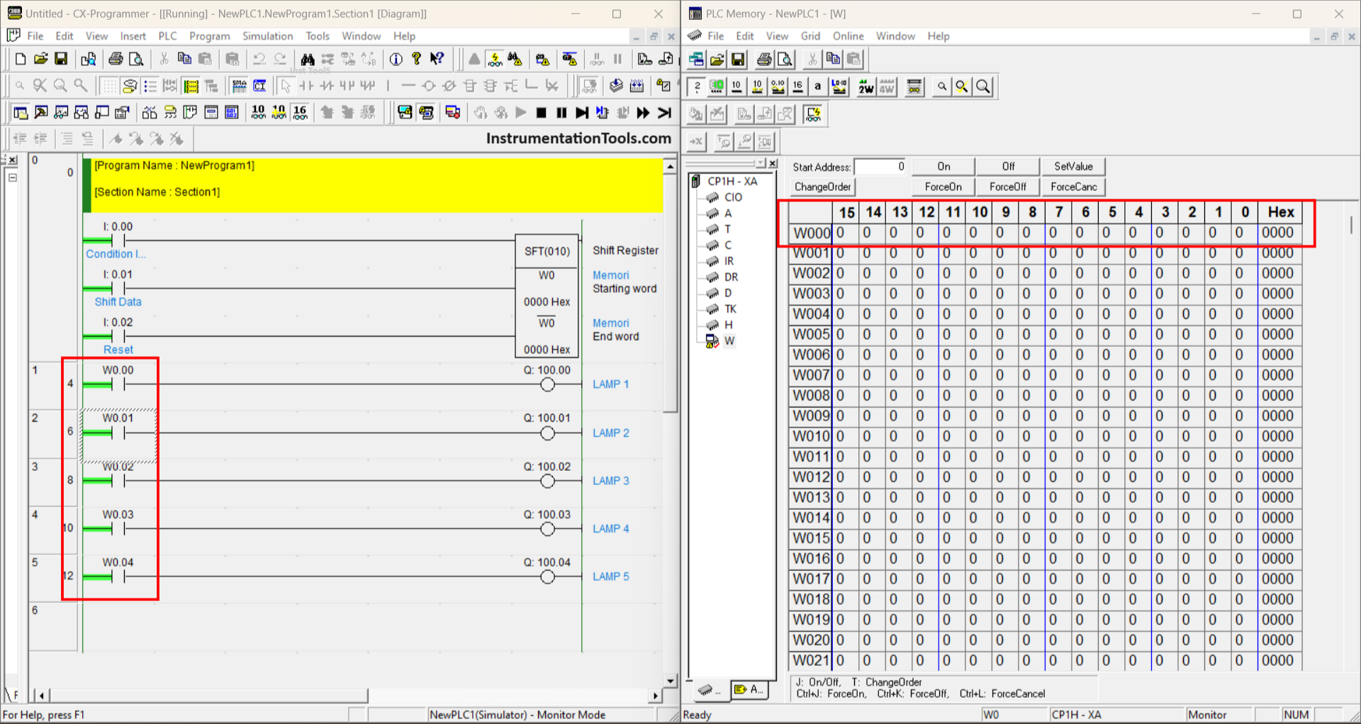
At the time, the Program is simulated, the contact condition on the ladder diagram and the value on Bits W0.00-W0.15 are still in the “False/0” condition.
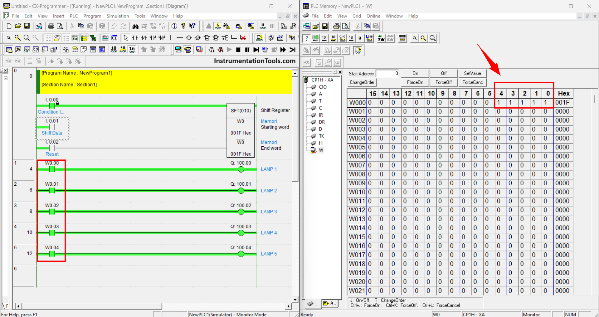
In the picture above is the condition when the Input Condition contact (0.00) is set ON and the Shift Data contact (0.01) has been executed 5 times.
The result is that 5 Bits of Word Memory W0 has been ACTIVE, starting from Bit W0.00-W0.04. It can be seen in the PLC Memory Pop-up that the condition of Bit W0.05-W0.15 is still in the “False/0” condition which means that the Bit is still not executed to the “True/1” condition.
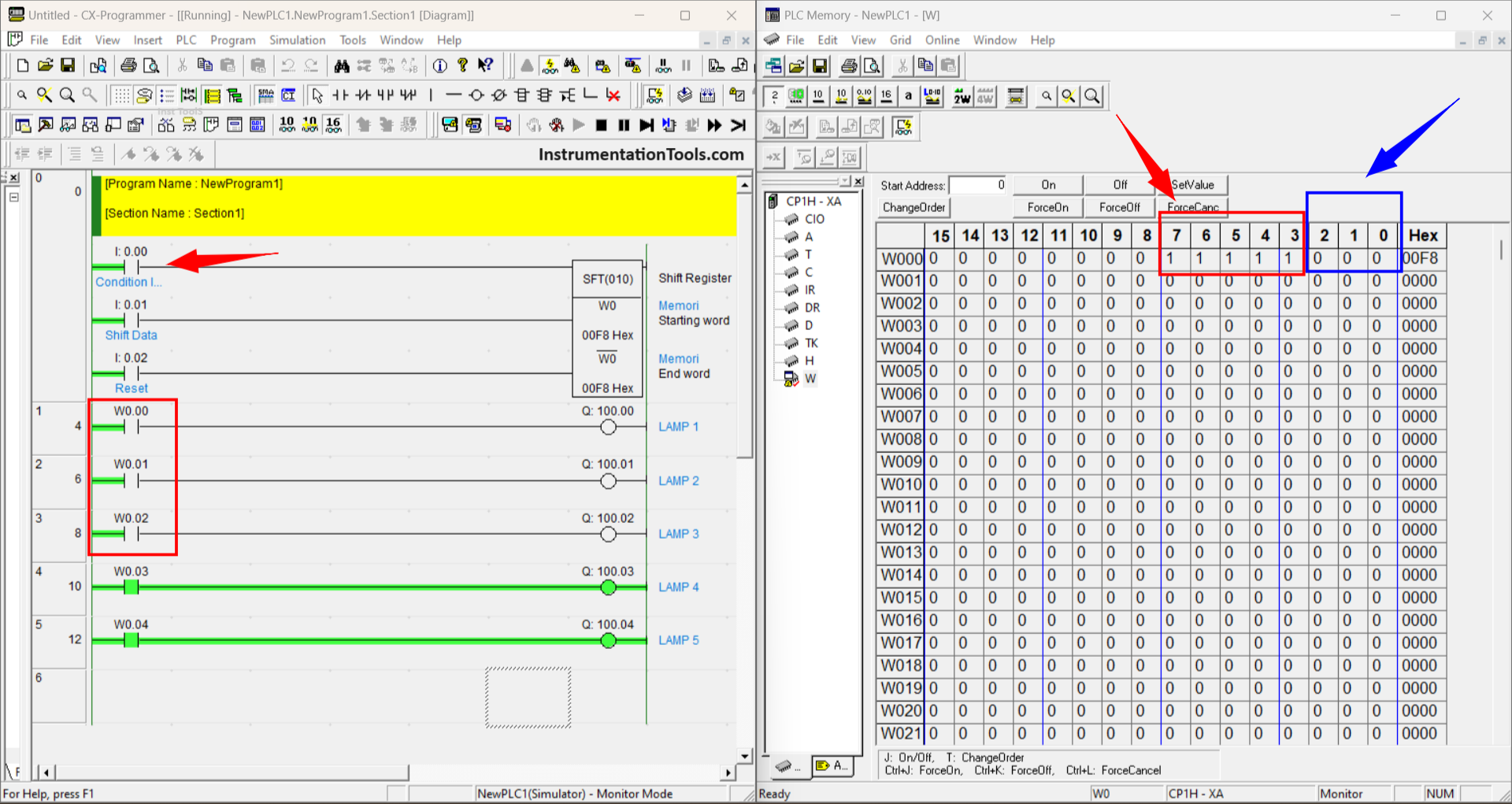
In this condition, the Condition Input contact (0.00) has been disabled and the Shift Data contact (0.01) has been executed 3 times. As a result, because the contact from Condition Input (0.00) is off, the condition is “False/0”.
A Shift Data contact (0.01) that has executed the condition 3 times so that it enters the value “False/0” into the Word Memory address W0.
In Pop-up, PLC Memory can also be seen if the value of W0.00-W0.02 has become “False / 0” and the previous condition shifted by 3 Bits so that Bit W0.05-W0.07 which was originally “False / 0” has become “True / 1”.
The picture above is the condition when contact Reset (0.02) is enabled then all Bit data in Word memory (W0) becomes “False/0”.
If you liked this article, please subscribe to our YouTube Channel for PLC and SCADA video tutorials.
You can also follow us on Facebook and Twitter to receive daily updates.
Read Next:
- CX-Programmer Products Sorting
- Pneumatic Cylinder & Motor Circuit
- Daily Alarm PLC Program using Clock
- Electrical Drives Speed Control Application
- STAR DELTA PLC Programming Control