Inst ToolsInst ToolsInst Tools
  • Ask
  • Courses
  • Videos
  • Q & A
    • Interview
      • Instrumentation
      • Electronics
      • Electrical
      • Practical Questions
    • MCQ
      • Instrumentation MCQ
      • Electrical MCQ
      • Electronics MCQ
      • Control Systems MCQ
      • Analog Electronics MCQ
      • Digital Electronics MCQ
      • Power Electronics MCQ
      • Microprocessor MCQ
      • Multiple Choice Questions
  • EE
    • Electronics
      • Electronics Q & A
      • Electronic Basics
      • Electronic Devices & Circuits
      • Electronics Animation
      • Digital Electronics
    • Electrical
      • Electrical Basics
      • Electrical Q & A
      • Power Electronics
      • Electrical Machines
      • Electrical Animation
      • Power Systems
      • Switchgear & Protection
      • Transmission & Distribution
  • Measure
    • Control Valves
    • Calibration
    • Temperature
    • Pressure
    • Flow
    • Level
    • Analyzers
    • Switches
    • Vibration
    • Solenoid Valve
  • Control
    • PLC Tutorials
    • Control Systems
    • Safety Instrumented System (SIS)
    • Communication
    • Fire & Gas System
  • More
    • Design
    • Tools
    • Animation
    • Basics
    • Formulas
    • Standards
    • TextBooks
    • Common
    • Software
    • Excel Tools
    • Erection & Commissioning
    • Process Fundamentals
    • Videos
    • Books
Search
All rights reserved. Reproduction in whole or in part without written permission is prohibited.
Reading: Concept of Interlocking in PLC
Share
Notification Show More
Font ResizerAa
Inst ToolsInst Tools
Font ResizerAa
  • Courses
  • PLC Tutorials
  • Control Systems
Search
  • Ask
  • Courses
  • Videos
  • Q & A
    • Interview
    • MCQ
  • EE
    • Electronics
    • Electrical
  • Measure
    • Control Valves
    • Calibration
    • Temperature
    • Pressure
    • Flow
    • Level
    • Analyzers
    • Switches
    • Vibration
    • Solenoid Valve
  • Control
    • PLC Tutorials
    • Control Systems
    • Safety Instrumented System (SIS)
    • Communication
    • Fire & Gas System
  • More
    • Design
    • Tools
    • Animation
    • Basics
    • Formulas
    • Standards
    • TextBooks
    • Common
    • Software
    • Excel Tools
    • Erection & Commissioning
    • Process Fundamentals
    • Videos
    • Books
Follow US
All rights reserved. Reproduction in whole or in part without written permission is prohibited.
Inst Tools > Blog > PLC Tutorials > Concept of Interlocking in PLC

Concept of Interlocking in PLC

Last updated: July 20, 2019 6:06 am
Editorial Staff
PLC Tutorials
1 Comment
Share
3 Min Read
SHARE

Design a ladder logic for Go-Down wiring for 3-rooms using plc programming and explain the Concept of Interlocking in PLC programs.

Contents
Interlocking in PLCArticles You May Like :
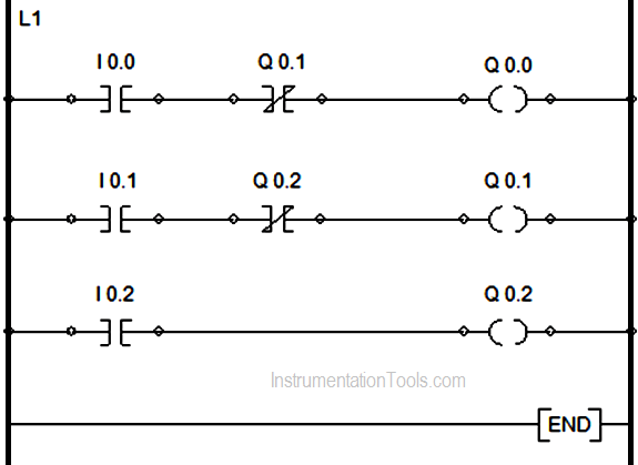
  • I0.0 , I0.1 , I0.2 : Toggle switches of corresponding rooms 1, 2, 3.
  • Q0.0 , Q0.1 , Q0.2 : Output coils (Bulbs) in room 1, 2 ,3.

Interlocking in PLC

Seeing the ladder diagram we can infer that as soon as the person enters into room 1 and switches ON the toggle switch 1 (I0.0), the bulb of that room  glows i.e, coil Q0.0  in rung 1 gets energized.
Concept of Interlocking in PLC

Now, the person moves into room 2 without switching OFF the toggle switch of room 1. As soon as he/she presses the toggle switch 2 (I0.1), the bulb of that room (Q0.1) starts glowing as its coil gets energized, while the bulb of room 1 itself goes OFF as its circuit is break by the interlock contact Q0.1 in rung 1 which is (N-C) type.

Similarly, when the goes into room 3 and presses switch 3 (I0.2) , the bulb of room 3 starts glowing and that of room 2 switches OFF keeping the bulb of room 1 already OFF. This is what we cover the going down from room 1 to room 2 to room 3.

Now as soon as the person wants to come back he/she again presses the toggle switch 3 (I0.2) which in turn breaks the circuit in rung 3 and the bulb (Q0.2) goes OFF. As soon as the bulb of room 3 goes OFF , the bulb of room 2 starts glowing again because here no longer the interlock contact Q0.0 remains open.

Similarly, pressing the toggle switch of room 2 (I0.1) switches OFF the bulb Q0.1 and in turn makes interlock contact Q0.l (N-C) from (N-O) and bulb of room 1 again start glowing by making the rung 1 logic TRUE. After pressing the toggle switch 1 (I0.0) again the bulb of room 1 i.e, Q0.0 goes OFF.
Articles You May Like :

PLC Interview Questions

Numbers and Symbols

One Pulse PLC Example

PLC Retentive Timer

Comparator PLC Blocks

Don't Miss Our Updates
Be the first to get exclusive content straight to your email.
We promise not to spam you. You can unsubscribe at any time.
Invalid email address
You've successfully subscribed !
Timers in Codesys – Timer ON, Timer OFF, Pulse Timer
How a PLC do the Scaling for a Sensor ?
From Boolean Algebra to PLC Logic
3 Phase Motor Control using PLC Ladder Logic
Grounding or Earthing Scheme in DCS or PLC Systems
Share This Article
Facebook Whatsapp Whatsapp LinkedIn Copy Link
Share
1 Comment
  • Ramu says:
    July 23, 2019 at 11:02 pm

    An interlock is a feature that makes the state of two mechanisms or functions mutually dependent. It may be used to prevent undesired states in a finite-state machine, and may consist of any electrical, electronic, or mechanical devices or systems.

    Now in case of PLC I will explain you by an example:

    Interlocks are conditions that must be TRUE in order for a particular output to be allowed to be energize.

    Standard motor circuit:.

    
       START       STOP                     PUMP1
    ----| |----+----| |----------------------( )
               |
       PUMP1   |
    ----| |----+
    

    But suppose we never want to dead-head the pump (run the pump without someplace for the fluid to go), and there are two valves, either of which can block the flow.

    And we never want to run the pump if there is an E-stop (even though the E-stop will be wired to an MCR (master control relay), it’s still better to be safe than sorry.)

    And we don’t want to run the pump if the high level switch is made.

    And we don’t want to run the pump, when pump 2 is running (because they both feed the same pipe, and the pressure would be too great).

    All of those become the interlock for the pump.

    
       START       STOP     VALVE_A     ESTOP   HI_LEVEL  PUMP2     PUMP1
    ----| |----+----| |---+---| |---+----| |------|/|------|/|-------( )
               |          |         | 
       PUMP1   |          | VALVE_B |
    ----| |----+          +---| |---+


    Note that the presence of the interlock conditions do not cause the pump to start – they just prevent it from starting if they aren’t there.

    The term interlock orginialy started from mechanical inter-locks, where one object would literally lock another object in place if the first one was moving, and vice versa. The term has broadened to include any prohibitive condition.

    You can understand the “inter-” part of the term when you realize that the code for pump2 would be the same as pump1, except that the pump1 contact would be the interlock instead of pump2

    Some programmers (including me) take all the interlock conditions and have them power a single coil. Whether you program that coil such that -|/|- or -| |- is used on the rung is a matter of personal taste. It’s also the source of much semantic confusion:

    “Pump1 is interlocked with pump2” – Does this men that you can’t run pump1 if pump2 is running, or do you mean that you can’t run pump1 until pump2 is running?

    “Right now, valve1 is Interlocked” – Does this mean that there is a condition preventing it from openning, or that it’s OK to open it?

    When you are working with someone on the interlock list, make sure you both understand which way you are talking.

    Hope it works for you

    Edit-1

    Kindly Consider NC contacts instead of NO Contacts for STOP and E- STOP.

    Reference – Quora

    Reply

Leave a Reply Cancel reply

Your email address will not be published. Required fields are marked *

Stay Connected

128.3kFollowersLike
69.1kFollowersFollow
208kSubscribersSubscribe
38kFollowersFollow

Categories

Recent Comments

  • Kamli on Top Free PLC Software
  • Guifty Shimica on Top Non-PLC Certification Courses for Automation Professionals
  • Guifty Shimica on Top Non-PLC Certification Courses for Automation Professionals
  • MIHARITSOA Aina Sitraka on Top Non-PLC Certification Courses for Automation Professionals

Related Articles

Siemens SIMATIC S7 PLC GSD File

How to import GSD files into the TIA Portal? – Siemens PLC

Allen Bradley SLC 500 PLC Programming

What is a Line Choke or Reactor in a VFD

What is a Line Choke or Reactor in a VFD?

TIA Portal Options

How to Troubleshoot Siemens PLC Programs?

PLC Training Course

#17 PLC Best Practices – Log PLC Uptime and Trend it on HMI

Reset Logic for pump Run Hours

PLC Program to Count Running Hours of any Equipment

Safety PLC Coding Practices

Safety PLC Coding Practices – Programming Recommendations

Configuration of Siemens Scada and PLC

Configuration of Input and Output Tags in Siemens Scada and PLC

More Articles

Turbidity Analyzer Working Principle

Turbidity Analyzer Working Principle

non-contact pyrometer principle

Non-contact Temperature Sensors

Thermocouple Extension Lead Problem

Thermocouple Extension Lead Problem

temperature sensor

Dead time

Omron PLC washing machine automation

Omron PLC Logic for Washing Machine Automation

Left-hand Rule for Current Carrying Conductors

Magnetism

Retentive ON delay timer using PLC Logic

Retentive ON Delay Timer using PLC

Siemens Process Mode

Test and Process Modes in Siemens PLC

Follow US
All rights reserved. Reproduction in whole or in part without written permission is prohibited.
Welcome Back!

Sign in to your account

Username or Email Address
Password

Lost your password?