Inst ToolsInst ToolsInst Tools
  • Courses
  • Automation
    • PLC
    • Control System
    • Safety System
    • Communication
    • Fire & Gas System
  • Instrumentation
    • Design
    • Pressure
    • Temperature
    • Flow
    • Level
    • Vibration
    • Analyzer
    • Control Valve
    • Switch
    • Calibration
    • Erection & Commissioning
  • Interview
    • Instrumentation
    • Electrical
    • Electronics
    • Practical
  • Q&A
    • Instrumentation
    • Control System
    • Electrical
    • Electronics
    • Analog Electronics
    • Digital Electronics
    • Power Electronics
    • Microprocessor
  • Request
Search
  • Books
  • Software
  • Projects
  • Process
  • Tools
  • Basics
  • Formula
  • Power Plant
  • Root Cause Analysis
  • Electrical Basics
  • Animation
  • Standards
  • 4-20 mA Course
  • Siemens PLC Course
Reading: What is Complementary Split Range Control (CSRC)?
Share
Font ResizerAa
Inst ToolsInst Tools
Font ResizerAa
  • Courses
  • Design
  • PLC
  • Interview
  • Control System
Search
  • Courses
  • Automation
    • PLC
    • Control System
    • Safety System
    • Communication
    • Fire & Gas System
  • Instrumentation
    • Design
    • Pressure
    • Temperature
    • Flow
    • Level
    • Vibration
    • Analyzer
    • Control Valve
    • Switch
    • Calibration
    • Erection & Commissioning
  • Interview
    • Instrumentation
    • Electrical
    • Electronics
    • Practical
  • Q&A
    • Instrumentation
    • Control System
    • Electrical
    • Electronics
    • Analog Electronics
    • Digital Electronics
    • Power Electronics
    • Microprocessor
  • Request
Follow US
All rights reserved. Reproduction in whole or in part without written permission is prohibited.
Inst Tools > Blog > Control Valves > What is Complementary Split Range Control (CSRC)?

What is Complementary Split Range Control (CSRC)?

Complementary split range control (CSRC) is a method where multiple control elements work together to regulate a single process variable.

Last updated: September 18, 2024 4:55 am
Viral Nagda
Control Valves PLC Tutorials
No Comments
Share
5 Min Read
SHARE

In industrial applications, there are times when a single control valve will not be able to control a process parameter like temperature or flow. In such applications, precision and high resolution of the process parameter is a must.

Contents
Complementary Split Range ControlCSRC ProcessAdvantages of CSRC control

But here, a single control valve will not be able to maintain such a requirement. So, there arises a need to use multiple control methods for a single process variable. In instrumentation, this method is called complementary split range control. In this post, we will see the concept of CSRC.

Complementary Split Range Control

The complementary split range control (CSRC) is a process where multiple control elements are employed and work in tandem to control a single process variable. The main thing to note here is that the control elements work in opposite directions with each other.

Complementary Split Range Control

Suppose there are two valves in a system, designed to control a single flow meter. In this case, if one valve is fully open, then the other will remain fully closed. In a case where the valve is analog, if one valve is 25% open, then the other valve will be 75% open.

In this complementary manner, the valves will coordinate with each other and control the final process. What is the main advantage of this? If one valve is allowed to pass one type of media and the other valve the other media, then when one valve is closing, the other valve will open simultaneously. It means that a proportional flow of media will flow to the final process.

Due to this, a proper mixture of media will always be maintained in the process. If there was a single valve, then it would have taken time for the media to settle its parameter; because the valve would either open or close only. CSRC thus controls a process parameter accurately and with fine resolution.

CSRC Process

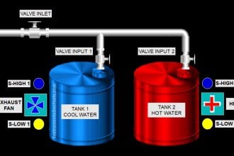
Consider a tank where a liquid is filled. The temperature of the liquid must be maintained accurately by the flow of hot and cold water. For both these types, two types of analog valves are used where one will pass hot water and the other valve will pass cold water. When one valve will open, the other valve will close, and vice-versa.

A PID controller will control both outputs inversely. At a desired cold setpoint, when one valve will start to open to pass cold water, the other valve will start to close to pass less hot water. Both the valves will be locked at a desired percentage to then pass an accurate amount of water mixture in the tank.

Similarly, at a desired hot setpoint, when one valve will start to open to pass hot water, the other valve will start to close to pass less cold water. As the setpoint is changed by the user, both the valves will work simultaneously and inversely to control the exact water temperature by maintaining proper water mixture flow.

Advantages of CSRC control

  1. As we saw, different types of media can be controlled in an inverse manner, which ensures a desired percentage of media presence, thus controlling the process parameter accurately.
  2. As the control elements work in a balanced way and avoid any full opening or closing at their best, the safety levels are high in this control. Due to this, the process can run smoothly without any safety hazards.
  3. With the multiple control elements, you can diversify your product by bringing in variations. And because these variations are under safe operation, business output too increases.
  4. Because the control elements are operating in inverse conditions, sudden jerks, mechanical imbalances, and process imbalances are reduced to a great extent.
  5. You can use CSRC control for redundancy too. This means if there are two valves, only one valve will operate at a time. The other valve will switch over in case of failure of the first valve.

In this way, we saw the concept of complementary split range control.

Read Next:

  • What is a Split Range Control Loop?
  • Types of SCADA System Architecture
  • SCADA and PLC Configuration Systems
  • Control Valve Sequence Methods
  • Split Range Control using Ladder Logic
Don't Miss Our Updates
Be the first to get exclusive content straight to your email.
We promise not to spam you. You can unsubscribe at any time.
Invalid email address
You've successfully subscribed !

Continue Reading

PLC Valve Control Ladder Logic Programming
Value Assignments in SCL Language – Single, Multiple, Combined
Solenoid Valve Problems and Solutions
How to Configure an Alarm in InTouch SCADA?
Heating and Mixing of Products using PLC Example Tutorial
How to use Master Control Reset (MCR) Instruction in PLC
Share This Article
Facebook Whatsapp Whatsapp LinkedIn Copy Link
Share
Leave a Comment

Leave a Reply Cancel reply

Your email address will not be published. Required fields are marked *

Stay Connected

128.3kFollowersLike
69.1kFollowersFollow
210kSubscribersSubscribe
38kFollowersFollow

Categories

Explore More

Control Algorithms in PLC Programming
How to Solve On-Off Valve Problems?
Exclusive Control Valve Sequence
#14 PLC Best Practices – Restrict Third-party Data Interfaces
Pneumatic Training Course – Download PDF
Compare Modbus, Fieldbus, and Profibus
Pressure Relief Valve Principle
Door Locking System – PLC Applications Examples

Keep Learning

PLC offline data of a project are compared

Compare Two Offline PLC Projects

valve trim characteristics

Control Valve Trim Characteristics

Volume Booster Working Principle

Control Valve Volume Booster Working Principle

What is a Servo Valve?

What is a Servo Valve? – Principle and Advantages

Needle Valve Body Design

What is Needle Valve ?

Pump and Mixer Operations Example PLC Timer-Based Control

Pump and Mixer Operations Example: PLC Timer-Based Control

Switched Mode Power Supply (SMPS)

How does SMPS Works? – Switched Mode Power Supply

Car Wash Program using Functional Block Diagram (PLC)

Car Wash Program using Functional Block Diagram (PLC)

Learn More

Filters in Compressors

Filters in Compressors

Electronic Devices & Circuits Objective Questions

Electronic Devices & Circuits Quiz – Set 2

Circuit diagram of Liquid level measurment using Adruino C

Level Measurement and Control using Arduino C

How to Design a Motor Faceplate in Graphics - SCADA Tutorials

How to Design a Motor Faceplate in Graphics? – SCADA Tutorials

Resistor-Color-Code-Chart

Resistor Color Code Animation

Siemens PLC Force LED

Forcing and Modifying PLC Logic

Electrostatic Precipitator

Principle of Operation of an Electrostatic Precipitator

Beta ratio ( β )

Important Factors in Flow Measurement

Menu

  • About
  • Privacy Policy
  • Copyright

Quick Links

  • Learn PLC
  • Helping Hand
  • Part Time Job

YouTube Subscribe

Follow US
All rights reserved. Reproduction in whole or in part without written permission is prohibited.
Welcome Back!

Sign in to your account

Username or Email Address
Password

Lost your password?