There are three leads in a transistor viz., emitter, base and collector terminals. However, when a transistor is to be connected in a circuit, we require four terminals; two for the input and two for the output. This difficulty is overcome by making one terminal of the transistor common to both input and output terminals. The input is fed between this common terminal and one of the other two terminals. The output is obtained between the common terminal and the remaining terminal. Accordingly; a transistor can be connected in a circuit in the following three ways :
(i) common base connection
(ii) common emitter connection
(iii) common collector connection
Each circuit connection has specific advantages and disadvantages. It may be noted here that regardless of circuit connection, the emitter is always biased in the forward direction, while the collector always has a reverse bias.
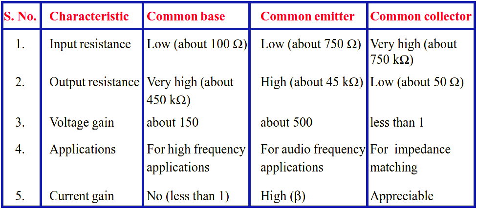
Comparison of Transistor Connections
The comparison of various characteristics of the three connections is given below.
Comparison of CB, CE & CC Amplifiers
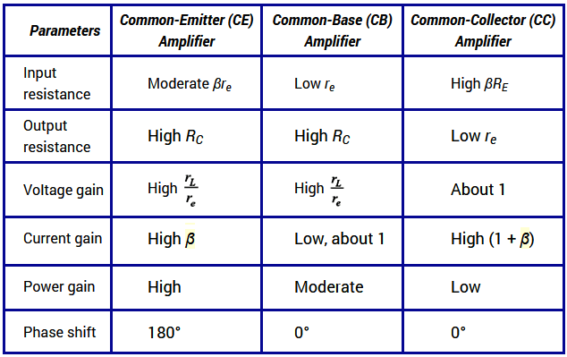
(i) CB Circuit
The input resistance (ri) of CB circuit is low because IE is high. The output resistance (ro) is high because of reverse voltage at the collector. It has no current gain (α < 1) but voltage gain can be high. The CB circuit is seldom used. The only advantage of CB circuit is that it provides good stability against increase in temperature.
(ii) CE Circuit
The input resistance (ri) of a CE circuit is high because of small IB. Therefore, ri for a CE circuit is much higher than that of CB circuit. The output resistance (ro) of CE circuit is smaller than that of CB circuit. The current gain of CE circuit is large because IC is much larger than IB. The voltage gain of CE circuit is larger than that of CB circuit. The CE circuit is generally used because it has the best combination of voltage gain and current gain. The disadvantage of CE circuit is that the leakage current is amplified in the circuit, but bias stabilisation methods can be used.
(iii) CC Circuit
The input resistance (ri) and output resistance (ro) of CC circuit are respectively high and low as compared to other circuits. There is no voltage gain (Av < 1) in a CC circuit. This circuit is often used for impedance matching.