Let’s study the working of coil type timers function in Siemens PLC programming.
Coil Type Timers
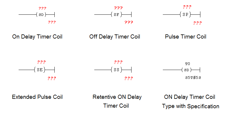
Different coil type timers available in PLC, they are
- ON Delay Timer Coil
- OFF Delay Timer Coil
- Pulse Timer Coil
- Extended Pulse Timer Coil
- Retentive ON Delay Timer Coil
- ON Delay Timer Coil with Specification.
As per the below diagram, the upper one (???) is the timer number (T0, T1, T2,….) and the lower one (???) is the timer preset value, the format is S5T#(Preset value in seconds) and its same for all remaining timers.
 ON Delay Timer Coil:
ON delay timer coil used for delaying ON condition of the output.
This output coil type timer needs one extra input contact (T0) to turn on its output. Reset coil from bit instructions needs to use separately to reset the timer.
OFF Delay Timer Coil:
OFF delay timer coil used for delaying the OFF condition of the output.
This output coil type timer needs one extra input contact (T0) to turn on its output. Reset coil from bit instructions needs to use separately to reset the timer.
Pulse Timer Coil:
When Timer receives a positive pulse from the input, it enables and using the timer input contact it enables output coil.
The timer will be in ON condition as long as the input condition is ON or accumulator value reaches the preset value.
If the input changed from “1 to 0” before the time interval has elapsed, the timer stopped along with disabling output. Reset coil from bit instructions needs to use separately to reset the timer.
Extended Pulse Coil:
When Timer receives a positive pulse at the input, it enables the output as long as the preset value set for the timer. The signal state at the output is at “1” as long as the timer is running.
If the input to the timer changed from “1 to 0” before the time interval has elapsed, the timer continues to run and enables output until the accumulator value reaches a preset value. Reset coil from bit instructions needs to use separately to reset the timer.
Retentive ON Delay Timer:
Same as ON delay timer except it does need input condition to remain ON.
It needs one single pulse to turn ON a timer. Reset coil from bit instructions needs to use separately to reset the timer.
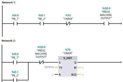
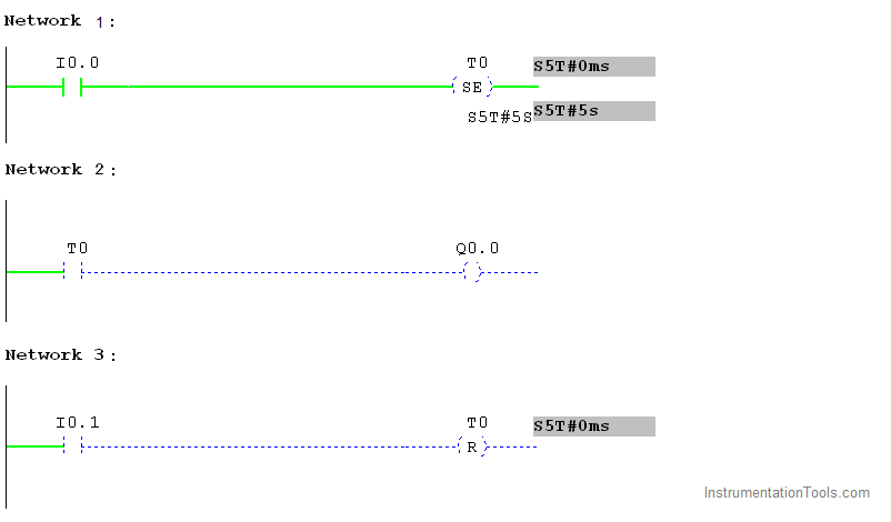
Ladder Logic – ON Delay Timer Coil
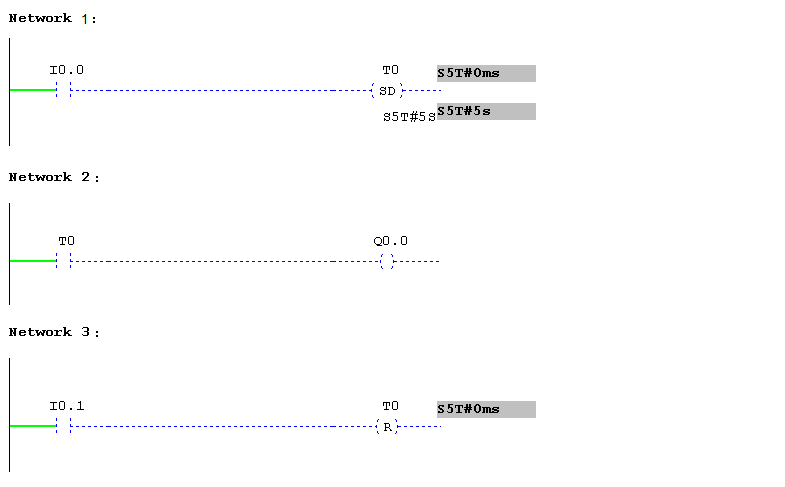
Network 1:
Input I0.0 is pressed, timer T0 make 5 seconds delay to turn ON Q0.0. The timer will go off if input I0.0 goes off in between. The preset value set to 5 seconds
Network 2:
Timer input contact T0 is used to turn on the output Q0.0 after 5 seconds
Network 3:
I0.1 input is used to reset the timer T0.
Ladder Logic – OFF Delay Timer Coil
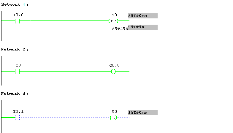
Network 1:
Input I0.0 is pressed, timer T0 enables, makes output Q0.0 to ON.
Network 2:
Timer input contact T0 is used to turn on the output Q0.0 immediately. But when I0.0 goes off, timer T0 makes 5 seconds delay to turn off Q0.0.
Network 3:
I0.1 input is used to reset the timer T0.
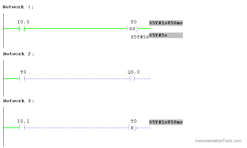
Ladder Logic – Pulse Timer Coil
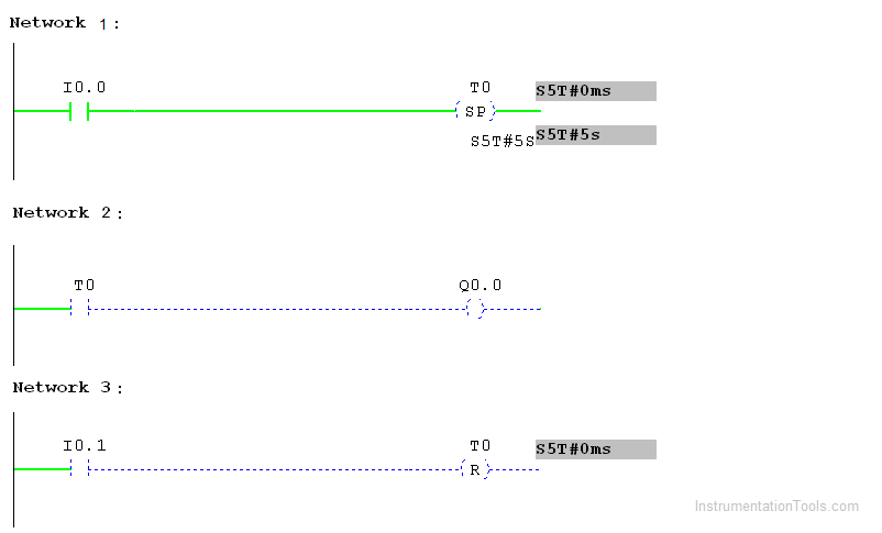
Network 1:
Input I0.0 is pressed, timer T0 started running up to accumulator value reaches a preset value. The timer will go off if input I0.0 goes off in-between make output also off
Network 2:
Timer input contact T0 is used to turn on the output Q0.0 for 5 seconds.
Network 3:
I0.1 input is used to reset the timer T0.
Ladder Logic – Extended Pulse Timer Coil
Network 1:
Input I0.0 is pressed, timer T0 started running up to accumulator value reaches a preset value. The timer will go off if input I0.0 goes off in-between make output to remains ON.
Network 2:
Timer input contact T0 is used to turn on the output Q0.0 for 5 seconds.
Network 3:
I0.1 input is used to reset the timer T0.
Ladder Logic – Retentive ON Delay Timer
Network 1:
Input I0.0 is pressed, timer T0 makes 5 seconds delay to turn on output Q0.0. The timer will be running if the input condition I0.0 goes off. The preset value set to 5 seconds.
Network 2:
Timer input contact T0 is used to turn on the output Q0.0 after 5 seconds. Even I0.0 goes off.
Network 3:
I0.1 input is used to reset the timer T0.
Author: Hema Sundaresan
If you liked this article, then please subscribe to our YouTube Channel for PLC and SCADA video tutorials.
You can also follow us on Facebook and Twitter to receive daily updates.
Read Next:
- OFF Delay Timer using PLC
- Retentive ON Delay Timer
- Control Instructions in PLC
- Up Counter PLC Program
- ON Delay Timer using PLC
- OFF versus ON Delay Timers