This Post explains the simple closed loop function with the example of Boiler Water Level Control System. This posts helpful to understand the basic principle of a Control loop and its components.
Steam boilers are very common in industry, principally because steam power is so useful. Common uses for steam in industry include doing mechanical work (e.g. a steam engine moving some sort of machine), heating, producing vacuums (through the use of “steam ejectors”), and augmenting chemical processes (e.g. reforming of natural gas into hydrogen and carbon dioxide).
The process of converting water into steam is quite simple: heat up the water until it boils. Anyone who has ever boiled a pot of water for cooking knows how this process works. Making steam continuously, however, is a little more complicated. An important variable to measure and control in a continuous boiler is the level of water in the “steam drum” (the upper vessel in a water-tube boiler).
In order to safely and efficiently produce a continuous flow of steam, we must ensure the steam drum never runs too low on water, or too high. If there is not enough water in the drum, the water tubes may run dry and burn through from the heat of the fire. If there is too much water in the drum, liquid water may be carried along with the flow of steam, causing problems downstream.
Boiler Water Level Control System
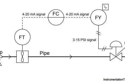
In this next illustration, you can see the essential elements of a water level control system, showing transmitter, controller, and control valve:
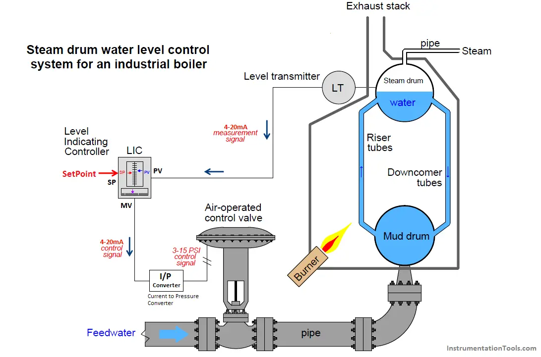
The first instrument in this control system is the level transmitter, or “LT”. The purpose of this device is to sense the water level in the steam drum and report (“transmit”) that measurement to the controller in the form of a signal.
In this case, the type of signal is electronic type DP Level Transmitter. The greater the water level in the drum, the more current signal output by the level transmitter. The level transmitter output will be in range of 4 to 20mA signal where 4mA is equal to 0% level signal and 20mA is 100% level signal.
The level transmitter will sent this measured level signal in the form of 4-20mA to the control system (PLC/DCS). In our example we have level control application, so we will use a level indicating controller, or “LIC” in the logic. The input device which is Level Transmitter and respective output device which is Control valve are connected to this “LIC” in the logic. Here input device (Level Transmitter) and Output device (Control Valve ) are real and Physical instruments installed in the field whereas the “LIC” is a soft logic in the PLC/DCS systems.
The purpose of this “LIC” is to compare the level transmitter’s signal against a setpoint value entered by a human operator representing the desired water level in the steam drum. The controller then generates an output signal telling the control valve to either introduce more or less water into the boiler to maintain the steam drum water level at setpoint. The controller output also be in the form of 4-20mA signal.
The last instrument in this control system loop is the control valve, operated directly by the air pressure signal output by the controller. Its purpose is to influence the flow rate of water into the boiler, “throttling” the water flow more or less as determined by controller. This particular type of control valve uses a large diaphragm and a large spring to move the valve further open with more signal pressure and further closed with less signal pressure.
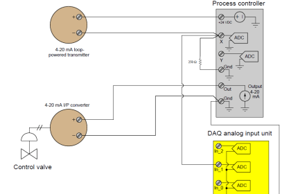
As the controller output is in the current form whereas the control operates on Pneumatic (Pressure). so we need an I/P Converter (current to pressure converter) to convert 4-20mA signal into equivalent standard 3-15psi signal. This I/P Converter can be a separate device added in between controller and control valve or it may be placed inbuilt the control valve.
When the controller is placed in the “automatic” mode, it will move the control valve to whatever position necessary to maintain a constant steam drum water level. The phrase “whatever position necessary” suggests the relationship between the controller output signal, the process variable signal (PV), and the setpoint (SP) is complex.
If the controller senses a water level above setpoint, it will close off the valve as far as necessary to decrease the water level down to setpoint. Conversely, if the controller senses a water level below setpoint, it will open up the valve as far as necessary to raise the water level up to setpoint.
What this means in a practical sense is that the controller’s output signal (equating to valve position) in automatic mode is just as much a function of process load (i.e. how much steam is being used from the boiler) as it is a function of setpoint (i.e. where we wish the water level to be). Consider a situation where the steam demand from the boiler is very low. If there isn’t much steam being drawn off the boiler, this means there will be little water boiled into steam and therefore little need for additional feedwater to be pumped into the boiler.
Therefore, in this situation, one would expect the control valve to hover near the fully-closed position, allowing just enough water into the boiler to keep the steam drum water level at setpoint. If, however, there is a high demand for steam from this boiler, the rate of evaporation will be much greater. This means the control system must add feedwater to the boiler at a much greater flow rate in order to maintain the steam drum water level at setpoint.
In this situation we would expect to see the control valve much closer to being fully-open as the control system “works harder” to maintain a constant water level in the steam drum. Thus, we see how the controller automatically positions the control valve to react to different boiler operating conditions even when the setpoint is fixed.
A human operator supervising this boiler has the option of placing the controller into “manual” mode. In this mode the control valve position is under direct control of the human operator, with the controller essentially ignoring the signal sent from the water level transmitter.
Being an indicating controller, the controller faceplate will still show how much water is in the steam drum, but it is now the human operator’s sole responsibility to move the control valve to the appropriate position to hold water level at setpoint – in manual mode the controller takes no corrective action of its own.
Manual mode is useful to human operators during start-up and shut-down conditions. It is also useful to instrument technicians for troubleshooting misbehaving control systems. Placing a controller into manual mode is akin to disengaging the cruise control in an automobile, transferring control of engine power from the car’s computer back to the human driver.
One can easily imagine an automobile mechanic needing to throttle a car’s engine “manually” (i.e. with the cruise control turned off) in order to properly diagnose an engine or drive train problem. This is true for industrial processes as well, where instrument technicians may need to place a controller into manual mode in order to properly diagnose transmitter or control valve problems.
