Inst ToolsInst ToolsInst Tools
  • Ask
  • Courses
  • Videos
  • Q & A
    • Interview
      • Instrumentation
      • Electronics
      • Electrical
      • Practical Questions
    • MCQ
      • Instrumentation MCQ
      • Electrical MCQ
      • Electronics MCQ
      • Control Systems MCQ
      • Analog Electronics MCQ
      • Digital Electronics MCQ
      • Power Electronics MCQ
      • Microprocessor MCQ
      • Multiple Choice Questions
  • EE
    • Electronics
      • Electronics Q & A
      • Electronic Basics
      • Electronic Devices & Circuits
      • Electronics Animation
      • Digital Electronics
    • Electrical
      • Electrical Basics
      • Electrical Q & A
      • Power Electronics
      • Electrical Machines
      • Electrical Animation
      • Power Systems
      • Switchgear & Protection
      • Transmission & Distribution
  • Measure
    • Control Valves
    • Calibration
    • Temperature
    • Pressure
    • Flow
    • Level
    • Analyzers
    • Switches
    • Vibration
    • Solenoid Valve
  • Control
    • PLC Tutorials
    • Control Systems
    • Safety Instrumented System (SIS)
    • Communication
    • Fire & Gas System
  • More
    • Design
    • Tools
    • Animation
    • Basics
    • Formulas
    • Standards
    • TextBooks
    • Common
    • Software
    • Excel Tools
    • Erection & Commissioning
    • Process Fundamentals
    • Videos
    • Books
Search
All rights reserved. Reproduction in whole or in part without written permission is prohibited.
Reading: Center Tapped Full Wave Rectifier Operation
Share
Notification Show More
Font ResizerAa
Inst ToolsInst Tools
Font ResizerAa
  • Courses
  • PLC Tutorials
  • Control Systems
Search
  • Ask
  • Courses
  • Videos
  • Q & A
    • Interview
    • MCQ
  • EE
    • Electronics
    • Electrical
  • Measure
    • Control Valves
    • Calibration
    • Temperature
    • Pressure
    • Flow
    • Level
    • Analyzers
    • Switches
    • Vibration
    • Solenoid Valve
  • Control
    • PLC Tutorials
    • Control Systems
    • Safety Instrumented System (SIS)
    • Communication
    • Fire & Gas System
  • More
    • Design
    • Tools
    • Animation
    • Basics
    • Formulas
    • Standards
    • TextBooks
    • Common
    • Software
    • Excel Tools
    • Erection & Commissioning
    • Process Fundamentals
    • Videos
    • Books
Follow US
All rights reserved. Reproduction in whole or in part without written permission is prohibited.
Inst Tools > Blog > Electronic Devices & Circuits > Center Tapped Full Wave Rectifier Operation

Center Tapped Full Wave Rectifier Operation

Last updated: October 4, 2016 12:56 pm
Editorial Staff
Electronic Devices & Circuits Electronics Animation
No Comments
Share
1 Min Read
SHARE

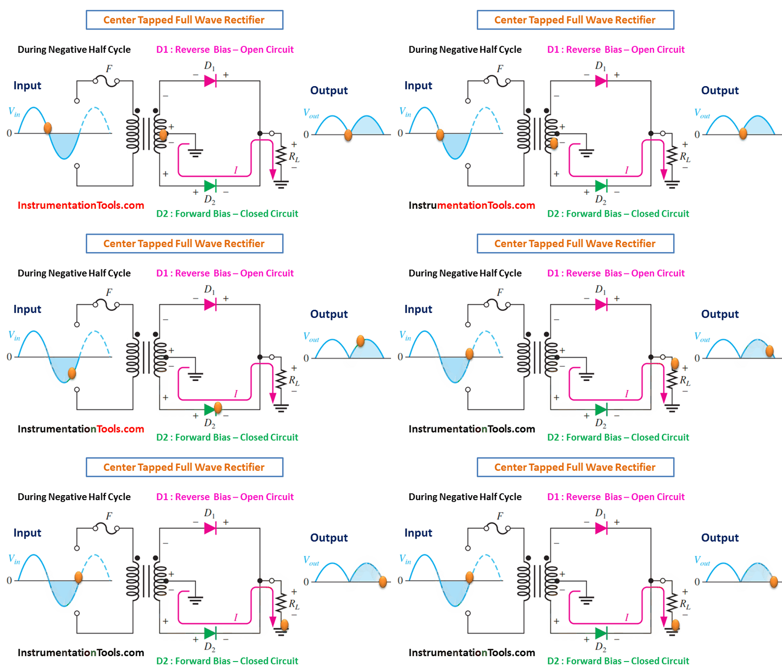
A center-tapped rectifier is a type of full-wave rectifier that uses two diodes connected to the secondary of a center-tapped transformer, as shown in Below Figure. The input voltage is coupled through the transformer to the center-tapped secondary. Half of the total secondary voltage appears between the center tap and each end of the secondary winding as shown.
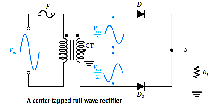
Center Tapped Full Wave Rectifier Operation

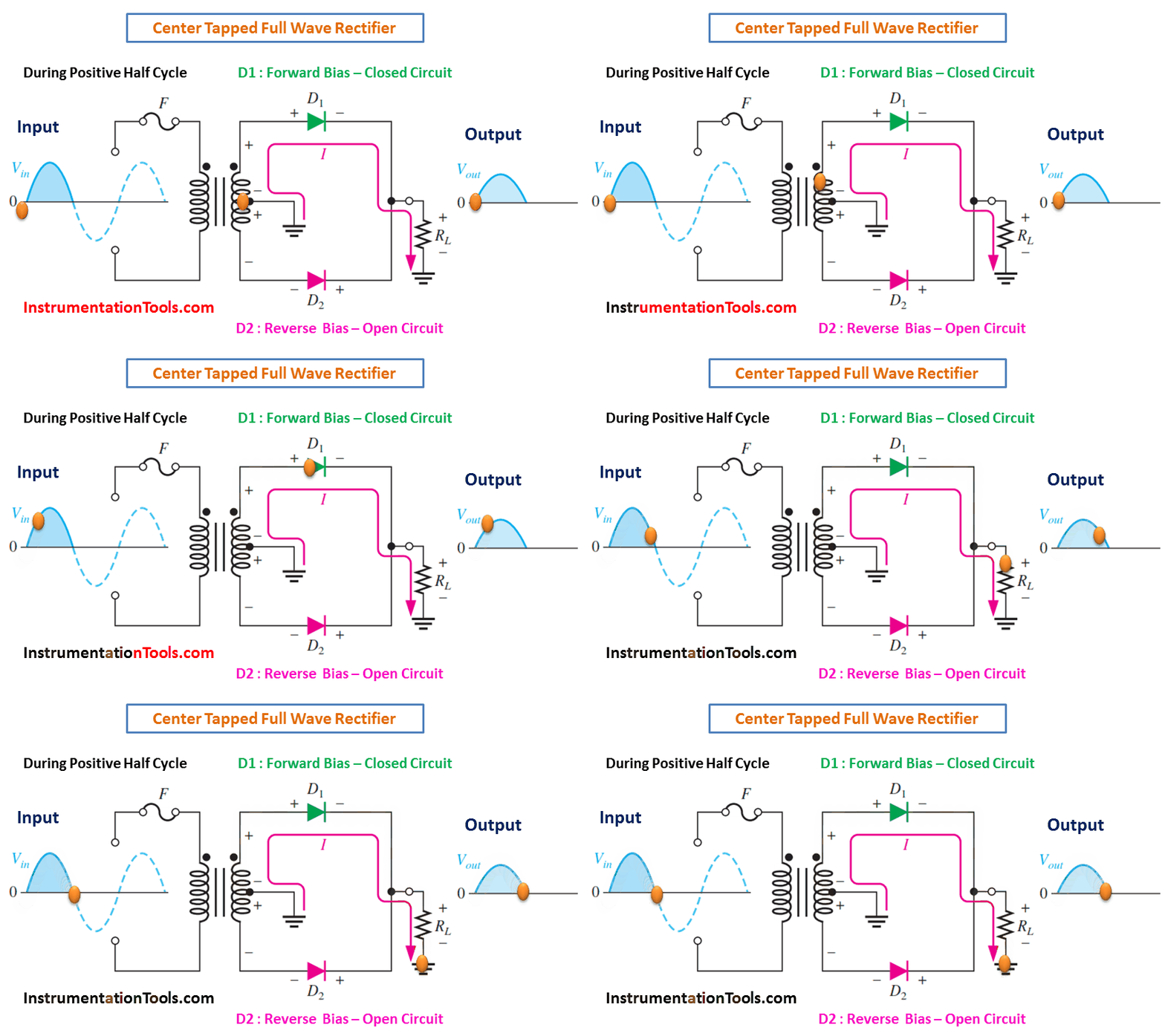
For a positive half-cycle of the input voltage, the polarities of the secondary voltages are as shown in Figure (a). This condition forward-biases diode D1 and reverse-biases diode D2. The current path is through D1 and the load resistor RL, as indicated.

For a negative half-cycle of the input voltage, the voltage polarities on the secondary are as shown in Figure (b). This condition reverse-biases D1 and forward-biases D2. The current path is through D2 and RL, as indicated. Because the output current during both the positive and negative portions of the input cycle is in the same direction through the load, the output voltage developed across the load resistor is a full-wave rectified dc voltage, as shown.

center-tapped-full-wave-rectifier-animation

(a) During positive half-cycles, D1 is forward-biased and D2 is reverse-biased.

Center Tapped Full Wave Rectifier Working Animation

(b) During negative half-cycles, D2 is forward-biased and D1 is reverse-biased.
Don't Miss Our Updates
Be the first to get exclusive content straight to your email.
We promise not to spam you. You can unsubscribe at any time.
Invalid email address
You've successfully subscribed !
Diode Limiters/Clippers Operation
Basics of Ohm’s Law
Laser Diode Working Principle
Applications of Photo diodes
PMMC Temperature Compensation
Share This Article
Facebook Whatsapp Whatsapp LinkedIn Copy Link
Share
Leave a Comment

Leave a Reply Cancel reply

Your email address will not be published. Required fields are marked *

Stay Connected

128.3kFollowersLike
69.1kFollowersFollow
208kSubscribersSubscribe
38kFollowersFollow

Categories

Recent Comments

  • Guifty Shimica on Top Non-PLC Certification Courses for Automation Professionals
  • Guifty Shimica on Top Non-PLC Certification Courses for Automation Professionals
  • MIHARITSOA Aina Sitraka on Top Non-PLC Certification Courses for Automation Professionals
  • Vaishnavi on Free Instrumentation Course for Trainee Engineers

Related Articles

Ethernet Switch Animation

Ethernet Bus Animation

Schottky Diode Vs PN junction Diode

Difference between Schottky Diode and PN junction Diode

Why Silicon is preferred over Germanium ?

Why Silicon is preferred over Germanium ?

Classification of Bridge Circuits

Classification of Bridge Circuits

p-type-semiconductor

N Type and P Type Semiconductors

pn-junction-with-depletion-layer

How a PN Junction Formed in a Diode

Field Instruments Questions and Answers

Basics of Amplifiers Interview Questions

energy-diagrams-for-insulator-semiconductor-and-conductor

Band Gap for Semiconductor Materials

More Articles

Measurement of Phase Angle Objective Questions

Measurement of Phase Angle Objective Questions

Spot Type Fixed Temperature Heat Detector Principle

Fixed Temperature Heat Detector Working Principle

Viscosity Measurement Objective Questions

Viscosity Measurement Objective Questions

Compressor IP Case Discharge Temperature Gradually Increases

Compressor IP Case Discharge Temperature Gradually Increases

Corona Discharge

Corona Discharge in Power Transmission Lines

Ladder Logic Counters Instruction

Up Counter PLC Program

hygrometer for measuring moisture

Difference Between Absolute and Relative Humidity

Digital Pressure Gauge Animation

Air Pressure Inside the Tank

Follow US
All rights reserved. Reproduction in whole or in part without written permission is prohibited.
Welcome Back!

Sign in to your account

Username or Email Address
Password

Lost your password?