This article will discuss the elevator system for transporting cargo using the XG5000 PLC programming. This elevator system is designed to operate on 3 floors. Elevators can only move Up or Down 1 floor. Each floor has a button to move to the required floor. Limit switch sensors on each floor are used to mark the elevator movement limits.
Program Objective
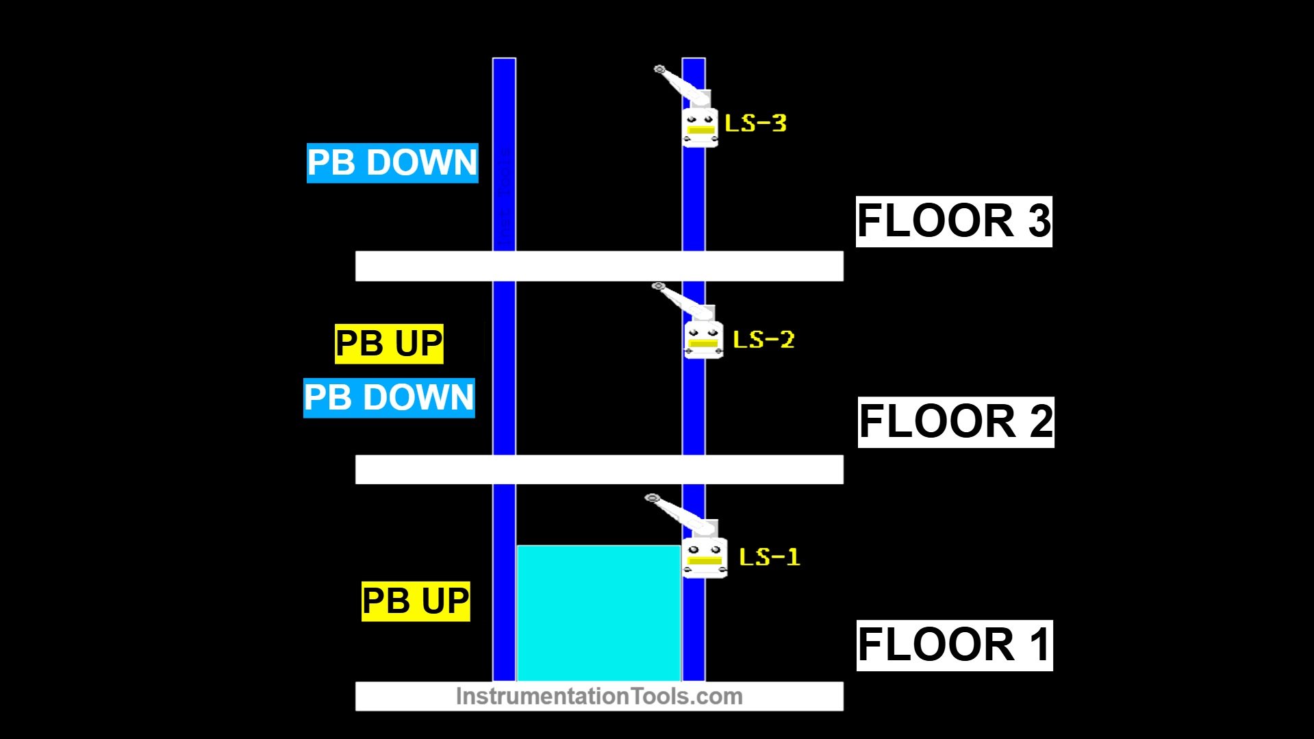
Floor 1:
- The elevator must already be on the 1st floor.
- There is 1 button (Up only).
- When the up button is pressed, the elevator will automatically move up to the 2nd floor.
- The elevator will stop when it reaches the 2nd floor.
Floor 2:
- The elevator must already be on the 2nd floor.
- There are 2 buttons (Up and Down).
- The up button will move the elevator to the 3rd floor.
- The down button will move the elevator to the 1st floor.
Floor 3:
- The elevator must already be on the 3rd floor.
- There is 1 button (Down only).
- When the Down button is pressed, the elevator will move down to the 2nd floor.
Limit Switch Sensor:
Each floor has a Limit Switch to detect the elevator’s position and ensure it stops at the desired floor.
3-Floor Cargo Elevator Program in XG5000
Mapping Details
| S.No. | Comment | Input (I) | Output (Q) | Memory Bit |
|---|---|---|---|---|
| 1 | START | P0000 | ||
| 2 | STOP | P0001 | ||
| 3 | LS_FLOOR1 | P0002 | ||
| 4 | PB_UP_FLOOR2 | P0003 | ||
| 5 | LS_FLOOR2 | P0004 | ||
| 6 | PB_UP_FLOOR3 | P0005 | ||
| 7 | LS_FLOOR3 | P0006 | ||
| 8 | PB_DOWN_FLOOR1 | P0007 | ||
| 9 | PB_DOWN_FLOOR2 | P0008 | ||
| 10 | FLOOR1_TO_2 | P0040 | ||
| 11 | FLOOR2_TO_3 | P0041 | ||
| 12 | FLOOR2_TO_1 | P0042 | ||
| 13 | FLOOR3_TO_2 | P0043 | ||
| 14 | SYSTEM_ON | M0000 |
Cargo Elevator System
RUNG 1 (START SYSTEM)
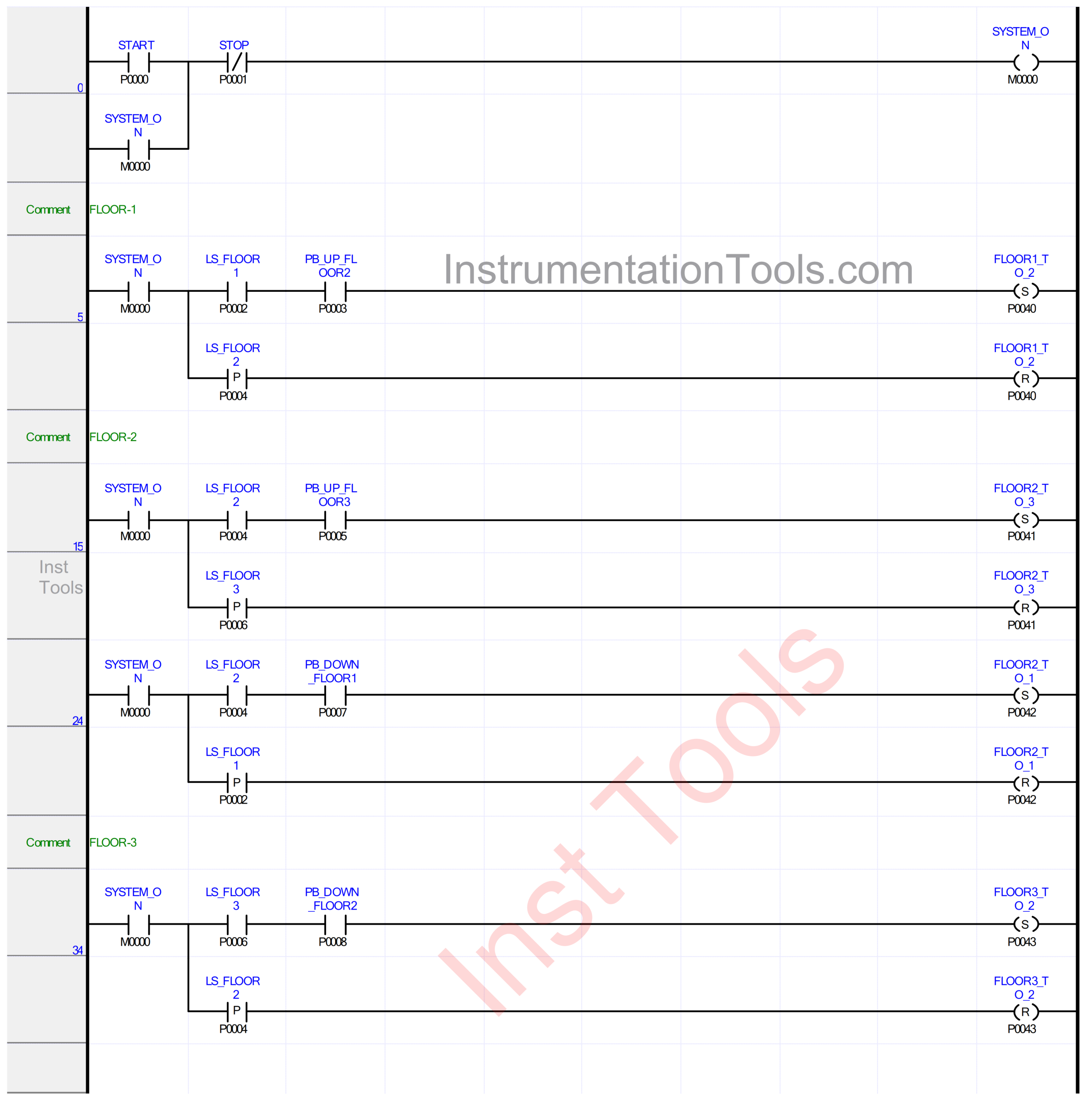
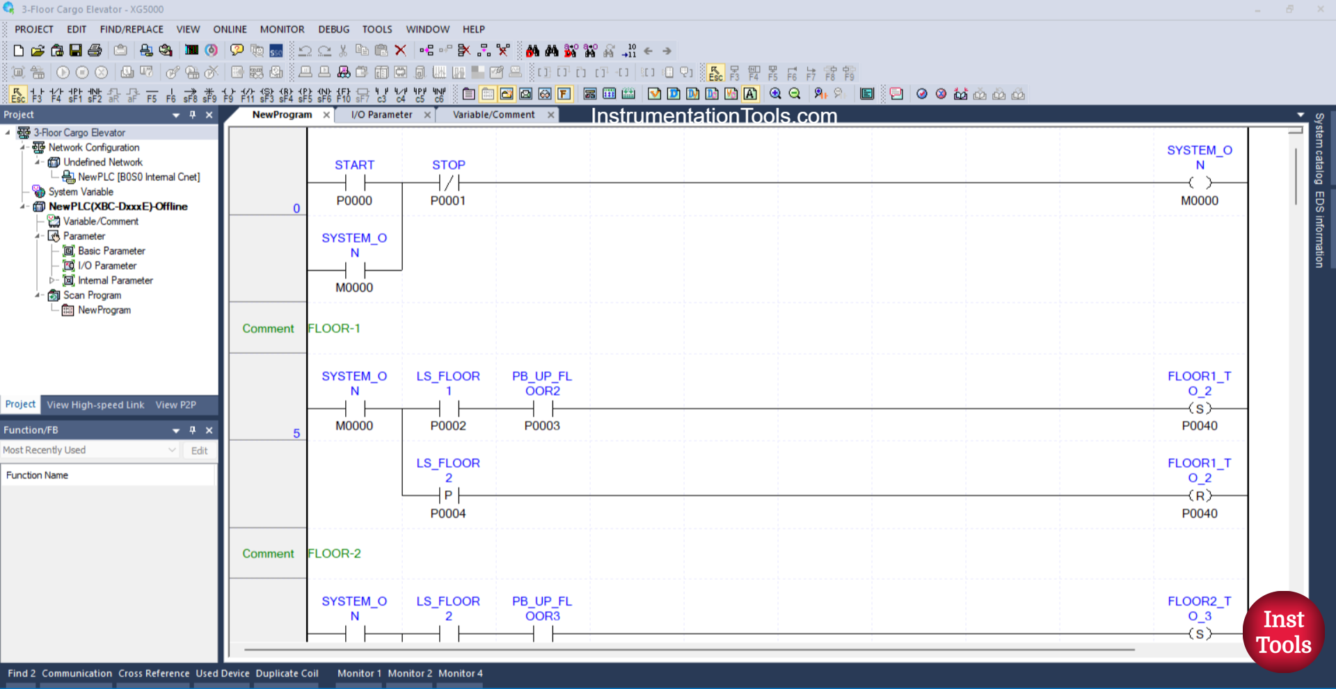
In this Rung, the memory bit SYSTEM_ON (M0000) will be in the HIGH state when the START (P0000) button is pressed. Because it uses Latching, the memory bit SYSTEM_ON (M0000) will remain in the HIGH state even though the START (P0000) button has been released.
The memory bit SYSTEM_ON (M0000) will be in the LOW state if the STOP (P0001) button is pressed.
RUNG 5 (FLOOR-1)
In this Rung, when the NO contact of the memory bit SYSTEM_ON (M0000) and the Limit Switch LS_FLOOR1 (P0002) are in the HIGH state and the PB_UP_FLOOR2 (P0003) button is pressed, the FLOOR1_TO_2 (P0040) output will be ON.
Because it uses the SET Coil Instruction, the output FLOOR1_TO_2 (P0040) will remain in the ON state even though the PB_UP_FLOOR2 (P0003) button has been released and the Limit Switch LS_FLOOR1 (P0002) is in the LOW state.
Next, when the Limit Switch LS_FLOOR2 (P0004) is in the HIGH state, the output FLOOR1_TO_2 (P0040) will be OFF. Because it uses the RESET Coil Instruction.
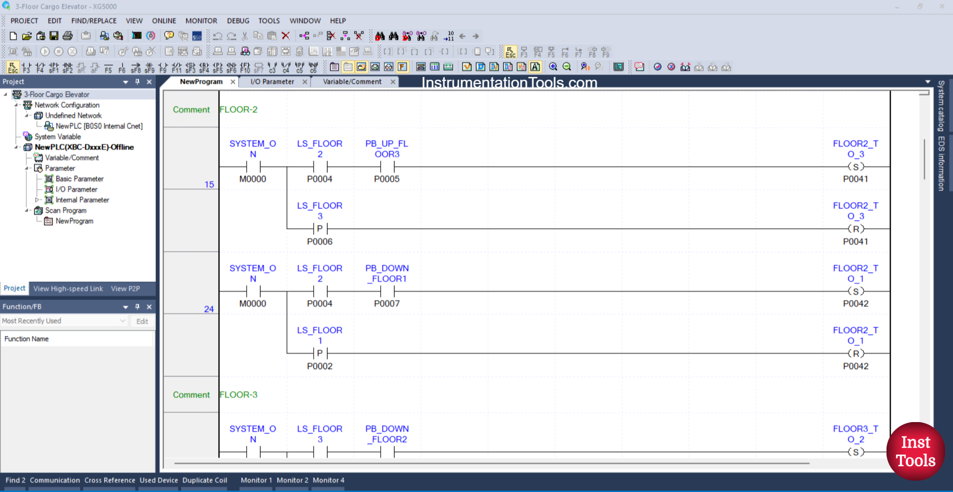
RUNG 15 (FLOOR-2)
In this Rung, when the NO contact of the memory bit SYSTEM_ON (M0000) and the Limit Switch LS_FLOOR2 (P0004) are in the HIGH state and the PB_UP_FLOOR3 (P0005) button is pressed, the FLOOR2_TO_3 (P0041) output will be ON.
Because it uses the SET Coil Instruction, the output FLOOR2_TO_3 (P0041) will remain in the ON state even though the PB_UP_FLOOR3 (P0005) button has been released and the Limit Switch LS_FLOOR2 (P0004) is in the LOW state.
Next, when the Limit Switch LS_FLOOR3 (P0006) is in the HIGH state, the output FLOOR2_TO_3 (P0041) will be OFF. Because it uses the RESET Coil Instruction.
RUNG 24
In this Rung, when the NO contact of the memory bit SYSTEM_ON (M0000) and the Limit Switch LS_FLOOR2 (P0004) are in the HIGH state and the PB_DOWN_FLOOR1 (P0007) button is pressed, the FLOOR2_TO_1 (P0042) output will be ON.
Because it uses the SET Coil Instruction, the output FLOOR2_TO_1 (P0042) will remain in the ON state even though the PB_DOWN_FLOOR1 (P0007) button has been released and the Limit Switch LS_FLOOR2 (P0004) is in the LOW state.
Next, when the Limit Switch LS_FLOOR1 (P0002) is in the HIGH state, the output FLOOR2_TO_1 (P0042) will be OFF. Because it uses the RESET Coil Instruction.
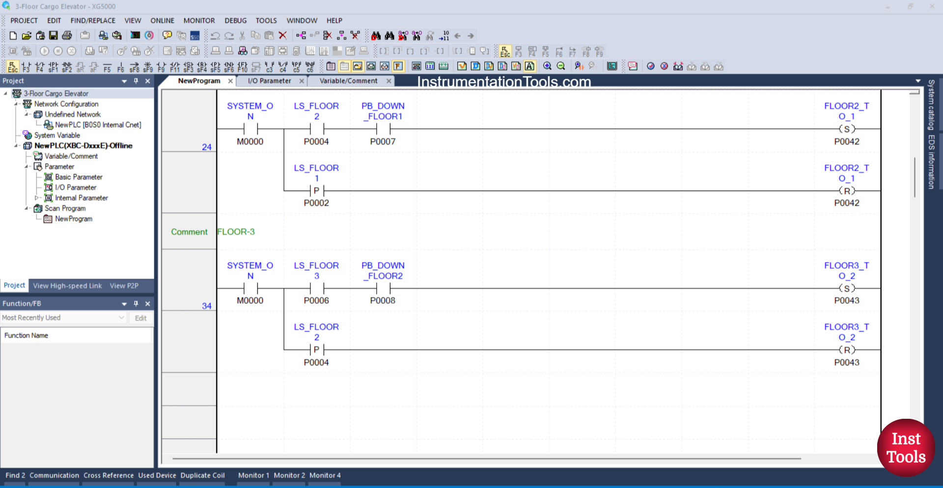
RUNG 34 (FLOOR-3)
In this Rung, when the NO contact of the memory bit SYSTEM_ON (M0000) and the Limit Switch LS_FLOOR3 (P0006) are in the HIGH state and the PB_DOWN_FLOOR2 (P0008) button is pressed, the FLOOR3_TO_2 (P0043) output will be ON.
Because it uses the SET Coil Instruction, the output FLOOR3_TO_2 (P0043) will remain in the ON state even though the PB_DOWN_FLOOR2 (P0008) button has been released and the Limit Switch LS_FLOOR3 (P0006) is in the LOW state.
Next, when the Limit Switch LS_FLOOR2 (P0004) is in the HIGH state, the output FLOOR3_TO_2 (P0043) will be OFF. Because it uses the RESET Coil Instruction.
Read Next:
- Flood Warning System using PLC Programming
- Object Detection Based Door Opening PLC System
- PLC Bottle Quality Inspection Using Vision Sensor
- Upload Option Disabled in Siemens PLC Tutorial
- PID Controller with Practical Example Explained