Inst ToolsInst ToolsInst Tools
  • Courses
  • Automation
    • PLC
    • Control System
    • Safety System
    • Communication
    • Fire & Gas System
  • Instrumentation
    • Design
    • Pressure
    • Temperature
    • Flow
    • Level
    • Vibration
    • Analyzer
    • Control Valve
    • Switch
    • Calibration
    • Erection & Commissioning
  • Interview
    • Instrumentation
    • Electrical
    • Electronics
    • Practical
  • Q&A
    • Instrumentation
    • Control System
    • Electrical
    • Electronics
    • Analog Electronics
    • Digital Electronics
    • Power Electronics
    • Microprocessor
  • Request
Search
  • Books
  • Software
  • Projects
  • Process
  • Tools
  • Basics
  • Formula
  • Power Plant
  • Root Cause Analysis
  • Electrical Basics
  • Animation
  • Standards
  • 4-20 mA Course
  • Siemens PLC Course
Reading: Calculate Power in Series RC Circuit
Share
Font ResizerAa
Inst ToolsInst Tools
Font ResizerAa
  • Courses
  • Design
  • PLC
  • Interview
  • Control System
Search
  • Courses
  • Automation
    • PLC
    • Control System
    • Safety System
    • Communication
    • Fire & Gas System
  • Instrumentation
    • Design
    • Pressure
    • Temperature
    • Flow
    • Level
    • Vibration
    • Analyzer
    • Control Valve
    • Switch
    • Calibration
    • Erection & Commissioning
  • Interview
    • Instrumentation
    • Electrical
    • Electronics
    • Practical
  • Q&A
    • Instrumentation
    • Control System
    • Electrical
    • Electronics
    • Analog Electronics
    • Digital Electronics
    • Power Electronics
    • Microprocessor
  • Request
Follow US
All rights reserved. Reproduction in whole or in part without written permission is prohibited.
Inst Tools > Blog > Electrical Theory > Calculate Power in Series RC Circuit

Calculate Power in Series RC Circuit

Last updated: August 2, 2018 12:17 am
Editorial Staff
Electrical Theory
No Comments
Share
1 Min Read
SHARE

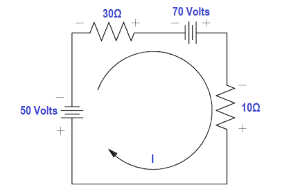
An 80 Ω XC and a 60 Ω resistance are in series with a 120V source, as shown in Figure.

Calculate Power in Series RC Circuit

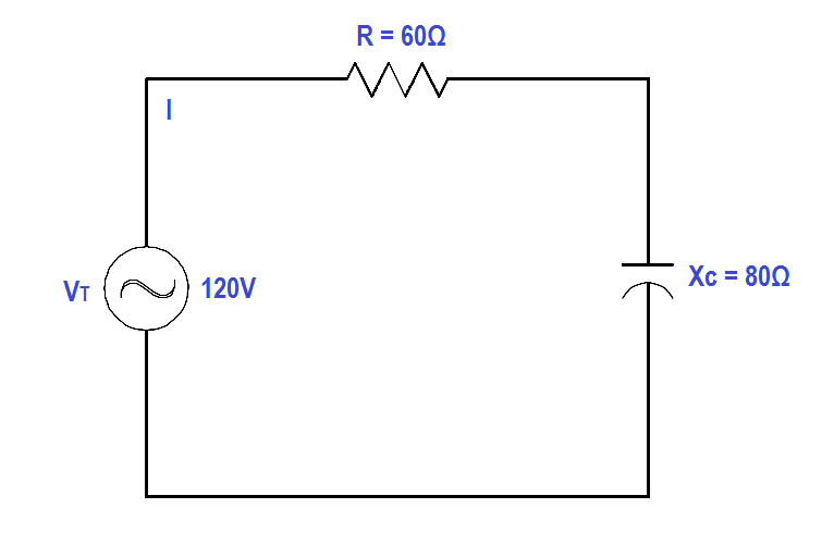
Figure : Series R-C Circuit

Find:

  1. Z
  2. Current, IT
  3. Power Factor, pf
  4. True Power, P
  5. Reactive Power, Q
  6. Apparent Power, S

Solution : 

1. Calculate Z

Z = √R2 + XC2

Z = √602 + 802

Z = 100 Ω

2.Current, IT

IT = VT/Z

IT = 120/100

IT = 1.2 amps

2. Calculate Power factor (pf)
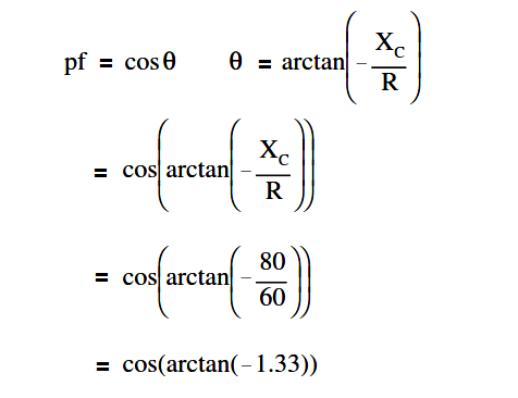
Calculate Power Factor in Series R-C Circuit

p.f. = cos (- 53º)

p.f. = 0.6

3. Calculate True Power, P
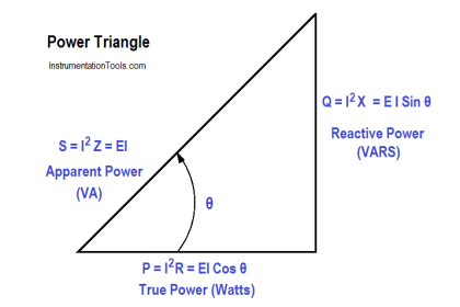
P = EI cos θ

P = (120)(1.2)(0.6)

P = 86.4 watts

4. Calculate Reactive Power, Q

Q = EI sin θ

Q = (120)(1.2)(0.798)

Q = 114.9 VAR

5. Calculate Apparent Power, S

S = EI

S = (120)(1.2)

S = 144 VA

Don't Miss Our Updates
Be the first to get exclusive content straight to your email.
We promise not to spam you. You can unsubscribe at any time.
Invalid email address
You've successfully subscribed !

Continue Reading

Parallel Open Circuit Faults
Ohm Meter
Resistivity
DC Motor Theory
Synchronous Motors
Transformer Impedance Ratio
Share This Article
Facebook Whatsapp Whatsapp LinkedIn Copy Link
Share
Leave a Comment

Leave a Reply Cancel reply

Your email address will not be published. Required fields are marked *

Stay Connected

128.3kFollowersLike
69.1kFollowersFollow
210kSubscribersSubscribe
38kFollowersFollow

Categories

Explore More

Power Factor Meter Principle
Resonance, Resonant Frequency, Series and Parallel Resonance
AC Generator Nameplate Ratings
Power in Balanced 3 Phase Loads
Electrical Wiring Terminology
Voltmeters
Series Open Circuit Faults
How to Measure Specific Gravity of Battery

Keep Learning

Two Wattmeters to Measure 3 Phase Power

Three Phase Wattmeter

Three-Phase Wye Wiring System

4-Wire, Three-Phase Wye Wiring System

Voltage Polarities

Voltage Polarity and Current Direction

DC Generator

DC Generator

Current Law

Applying Kirchhoff’s Current Law

3-Wire, Three-Phase Delta Wiring System

3-Wire, Three-Phase Delta Wiring System

Ground Detector Lamp Method Principle

Ground Detector Principle

Auto Transformer Schematic

Classification of Transformers

Learn More

Communicate between the PLC program and HMI program

Design a Program Using Studio 5000 and FactoryTalk View Studio

Control Valve Tips and Tricks

Control Valve Tips and Tricks

pressure switches relay circuit

Determine the functions of Pressure Switches ?

PLC Programming Example on Bottle Line Control

PLC Programming Example on Bottle Line Control

Digital Electronics Multiple Choice Questions

Controlled Inverter Objective Questions

Combining Independent Current Sources in Parallel

Combining Independent Current Sources in Parallel

Nuclear Plant Sensors and Detectors Quiz

Nuclear Plant Sensors and Detectors Quiz

Process Dynamics and PID Controller Tuning

Process Dynamics and PID Controller Tuning

Menu

  • About
  • Privacy Policy
  • Copyright

Quick Links

  • Learn PLC
  • Helping Hand
  • Part Time Job

YouTube Subscribe

Follow US
All rights reserved. Reproduction in whole or in part without written permission is prohibited.
Welcome Back!

Sign in to your account

Username or Email Address
Password

Lost your password?