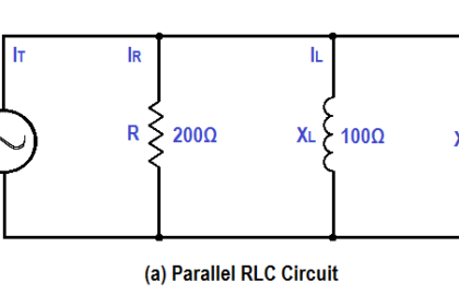
A 600 Ω resistor and 200 Ω XL are in parallel with a 440V source, as shown in Figure.
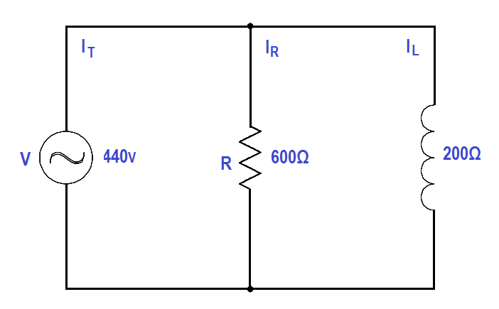
Figure : Parallel R-L Circuit
Find:
- Current, IT
- Power Factor, pf
- True Power, P
- Reactive Power, Q
- Apparent Power, S
Solution:
1.Current, IT
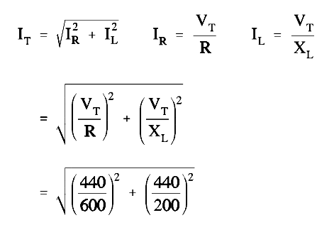
IT = 2.3 amps
2. Calculate Power factor (pf)
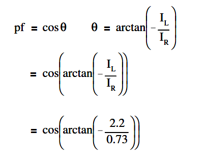
p.f. = cos (- 71.5º)
p.f. = 0.32
3. Calculate True Power, P
P = EI cos θ
P = (440)(2.3)(0.32)
P = 323.84 watts
4. Calculate Reactive Power, Q
Q = EI sin θ
Q = (440)(2.3)(0.948)
Q = 959.4 VAR
5. Calculate Apparent Power, S
S = EI
S = (440)(2.3)
S = 1012 VA