Inst ToolsInst ToolsInst Tools
  • Ask
  • Courses
  • Videos
  • Q & A
    • Interview
      • Instrumentation
      • Electronics
      • Electrical
      • Practical Questions
    • MCQ
      • Instrumentation MCQ
      • Electrical MCQ
      • Electronics MCQ
      • Control Systems MCQ
      • Analog Electronics MCQ
      • Digital Electronics MCQ
      • Power Electronics MCQ
      • Microprocessor MCQ
      • Multiple Choice Questions
  • EE
    • Electronics
      • Electronics Q & A
      • Electronic Basics
      • Electronic Devices & Circuits
      • Electronics Animation
      • Digital Electronics
    • Electrical
      • Electrical Basics
      • Electrical Q & A
      • Power Electronics
      • Electrical Machines
      • Electrical Animation
      • Power Systems
      • Switchgear & Protection
      • Transmission & Distribution
  • Measure
    • Control Valves
    • Calibration
    • Temperature
    • Pressure
    • Flow
    • Level
    • Analyzers
    • Switches
    • Vibration
    • Solenoid Valve
  • Control
    • PLC Tutorials
    • Control Systems
    • Safety Instrumented System (SIS)
    • Communication
    • Fire & Gas System
  • More
    • Design
    • Tools
    • Animation
    • Basics
    • Formulas
    • Standards
    • TextBooks
    • Common
    • Software
    • Excel Tools
    • Erection & Commissioning
    • Process Fundamentals
    • Videos
    • Books
Search
All rights reserved. Reproduction in whole or in part without written permission is prohibited.
Reading: Bently Nevada Vibration Probes Functional Testing
Share
Notification Show More
Font ResizerAa
Inst ToolsInst Tools
Font ResizerAa
  • Courses
  • PLC Tutorials
  • Control Systems
Search
  • Ask
  • Courses
  • Videos
  • Q & A
    • Interview
    • MCQ
  • EE
    • Electronics
    • Electrical
  • Measure
    • Control Valves
    • Calibration
    • Temperature
    • Pressure
    • Flow
    • Level
    • Analyzers
    • Switches
    • Vibration
    • Solenoid Valve
  • Control
    • PLC Tutorials
    • Control Systems
    • Safety Instrumented System (SIS)
    • Communication
    • Fire & Gas System
  • More
    • Design
    • Tools
    • Animation
    • Basics
    • Formulas
    • Standards
    • TextBooks
    • Common
    • Software
    • Excel Tools
    • Erection & Commissioning
    • Process Fundamentals
    • Videos
    • Books
Follow US
All rights reserved. Reproduction in whole or in part without written permission is prohibited.
Inst Tools > Blog > Calibration > Bently Nevada Vibration Probes Functional Testing

Bently Nevada Vibration Probes Functional Testing

Last updated: June 15, 2022 9:43 am
Editorial Staff
Calibration Guest Articles Vibration Measurement
9 Comments
Share
3 Min Read
SHARE

Bently Nevada Vibration Probes Functional Testing

Contents
Objective :Principle:Required tools:Equipment Setup:Proximitor Calibration graph :

Objective :

To check the characteristics and healthiness of vibration probes ( make : Bently Nevada )

Principle:

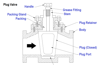
Proximity transducers use Eddy Current principle to measure the distance between the probe Tip and the surface to be observed.

The proximeter generate a low power radio frequency (RF) signal. This RF signal is connected to a coil of wire inside the probe tip by the extension cable.

When No conductive material is within the range of RF signal which surrounds the probe tip, virtually all of the power released to the surrounding area is returned to the probe.

When a conductive surface approaches the probe tip, the RF signal sets up small eddy currents on the surface. These eddy currents creates a measurable power loss in the RF signal.

When vibration tip nearer the target the greater the power loss. The system uses this power loss to generate as output voltage.

The output voltage of the proximeter is linearly proportional to gap over a wide range.

Required tools:

  • Multimeter
  • Micrometer
  • TK-3

Also Read : What is TK-3
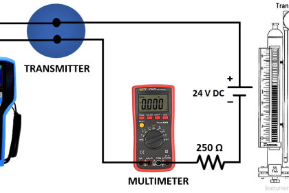
Equipment Setup:

To check the characteristic of vibration probe

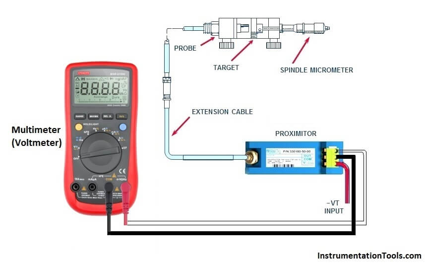
Procedure: Follow the following steps

1) Physically check the vibration probe and extension cable for any damages, if it is please Replace with new one.

2) Check resistance of vibration probe and continuity of extension cable it should be in between 5 To 9Ω and 5 to 20 Ω (resistance value varies from model to model)

3) Place the vibration probe on TK-3 spindle and adjust to the target plate surface and make sure the scale should be zero.

4) Connect multimeter on proximeter common and Vout terminals. Apply input voltage.

5) Measure the output voltage (multimeter reading) and increase the target distance in the TK-3 calibrator and follow the same steps as per given table and note down the output voltages at different displacements (gaps).

Bently Nevda Vibration Probes Voltage

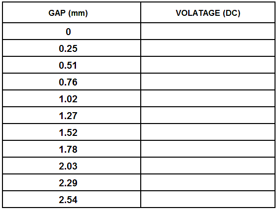
6) After this make a graph which shows the relation between gap and voltage.

7) If graph is linear in between 10 mils to 80 mils then probe is in good condition.

Vibration Probe Calibration

Proximitor Calibration graph :

Bently Nevda Vibration Probes Calibration

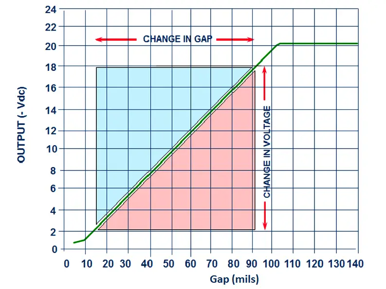
Note : Change in gap is within 80 mils Linear Range which is in between 10 mils and 90 mils

Article by :
Ashish Agrawal
Don't Miss Our Updates
Be the first to get exclusive content straight to your email.
We promise not to spam you. You can unsubscribe at any time.
Invalid email address
You've successfully subscribed !
Ultrasonic Level Transmitter Principle, Limitations, Calibration and configuration
What is calibration?
Oxidation-Reduction Potential (ORP) Sensor Calibration Procedure
How to Calibrate pH Electrode?
Foundation Fieldbus Transmitter Calibration
Share This Article
Facebook Whatsapp Whatsapp LinkedIn Copy Link
Share
9 Comments
  • rakhi rawat says:
    October 21, 2017 at 8:38 am

    its a very good n easy for learn i like too much this article

    Reply
  • prasanth says:
    October 26, 2017 at 3:42 pm

    Why using negative voltage? -24vdc

    Reply
    • S Bharadwaj Reddy says:
      October 26, 2017 at 3:45 pm

      Hi, check this article, CLICK HERE

      Reply
  • azetou says:
    October 31, 2017 at 2:16 pm

    Thank you for the article, there is a mistake in the graph though : Gap is in mils not in millimeters.

    Reply
    • S Bharadwaj Reddy says:
      October 31, 2017 at 3:44 pm

      Corrected. Thanks for your efforts & updates.

      Reply
  • ashraf says:
    April 15, 2018 at 11:40 pm

    Incremental Scale Factor (ISF) is just as important as Average Scale Factor (ASF). For a better proximity transducer system verification, one can easily refer to Bently Manuals. They have written the procedure in a clear and concise manner.

    Another important thing, need to confirm machinery shaft material as well whether the proximitor used is modified for linearity other than AISI 4140 (typical material for shaft). You can see physically a ‘MOD’ sticker with details on it, on the side of the proximitor itself. Performing a verification check using a MOD proximitor against a standard AISI 4140 spindle micrometer will render the result invalid.

    Reply
    • RAMASAMY GANAPATHY says:
      August 8, 2023 at 2:10 pm

      In Bently Neveda Vibration Measurement, Some Equipments are having Proximitor sensor model like 330180-X1 not having scale factor 200mv/mil. Because it not Calibrated by AISI 4140 but by some other metal target place. In that case , we should not use 4140 target material disc. We have to buy corresponding material target button.

      Reply
      • paco says:
        May 19, 2025 at 10:29 pm

        Hola buen dia, podras compartir mas informacion al respecto. te lo agradeceria

        Reply
  • Breaker says:
    November 13, 2018 at 4:04 pm

    i couldn’t find the manual from bently nevada that talks about the procedure for checking or calibration te sensor*proximiter , could you please refere to this document or give me the link to it thanks

    Reply

Leave a Reply Cancel reply

Your email address will not be published. Required fields are marked *

Stay Connected

128.3kFollowersLike
69.1kFollowersFollow
208kSubscribersSubscribe
38kFollowersFollow

Categories

Recent Comments

  • Guifty Shimica on Top Non-PLC Certification Courses for Automation Professionals
  • Guifty Shimica on Top Non-PLC Certification Courses for Automation Professionals
  • MIHARITSOA Aina Sitraka on Top Non-PLC Certification Courses for Automation Professionals
  • Vaishnavi on Free Instrumentation Course for Trainee Engineers

Related Articles

Accelerometer Vibration Probe

Accelerometer Vibration Probe Principle

calibration potentiometer for simulating the millivoltage output

Temperature Standards

Two Out of Three Logic

Alarm and Trip Systems

Magnetostrictive Level Transmitter Calibration

Magnetostrictive Level Transmitter Calibration Procedure

Chocked flow

Control Valve Cavitation and Flashing

Junction Box Wiring

4-20mA Junction Box versus Fieldbus (FF) Junction Box

IS Loop Formula

Difference between Intrinsic Safe and Non-Intrinsic Safe Cables

Error sources creating Uncertainty in calibration

Error sources creating uncertainty in Calibration

More Articles

Calculate Power in Parallel RC Circuit

Calculate Power in Parallel RC Circuit

Thermocouple cold junction compensation

Why Thermocouple Reference Junction Compensation Required ?

Electrical Drives and Controls Interview Questions

Electrical Drives and Controls Interview Questions

Displacer Level Measurement Formula

Displacer Level Measurement Calculations

PLC Circuit Answers

PLC connected to Three Pushbutton Switches

PLC Modbus Communication

Introduction to Modbus – Reading and Writing Data

Digital Electronics Projects

Top 100 Digital Electronics Project Ideas for Engineering Students

Alternator Objective Questions and Answers

125+ Alternator Objective Questions and Answers

Follow US
All rights reserved. Reproduction in whole or in part without written permission is prohibited.
Welcome Back!

Sign in to your account

Username or Email Address
Password

Lost your password?