Inst ToolsInst ToolsInst Tools
  • Courses
  • Automation
    • PLC
    • Control System
    • Safety System
    • Communication
    • Fire & Gas System
  • Instrumentation
    • Design
    • Pressure
    • Temperature
    • Flow
    • Level
    • Vibration
    • Analyzer
    • Control Valve
    • Switch
    • Calibration
    • Erection & Commissioning
  • Interview
    • Instrumentation
    • Electrical
    • Electronics
    • Practical
  • Q&A
    • Instrumentation
    • Control System
    • Electrical
    • Electronics
    • Analog Electronics
    • Digital Electronics
    • Power Electronics
    • Microprocessor
  • Request
Search
  • Books
  • Software
  • Projects
  • Process
  • Tools
  • Basics
  • Formula
  • Power Plant
  • Root Cause Analysis
  • Electrical Basics
  • Animation
  • Standards
  • 4-20 mA Course
  • Siemens PLC Course
Reading: Belt Sway Switch Working Principle
Share
Font ResizerAa
Inst ToolsInst Tools
Font ResizerAa
  • Courses
  • Design
  • PLC
  • Interview
  • Control System
Search
  • Courses
  • Automation
    • PLC
    • Control System
    • Safety System
    • Communication
    • Fire & Gas System
  • Instrumentation
    • Design
    • Pressure
    • Temperature
    • Flow
    • Level
    • Vibration
    • Analyzer
    • Control Valve
    • Switch
    • Calibration
    • Erection & Commissioning
  • Interview
    • Instrumentation
    • Electrical
    • Electronics
    • Practical
  • Q&A
    • Instrumentation
    • Control System
    • Electrical
    • Electronics
    • Analog Electronics
    • Digital Electronics
    • Power Electronics
    • Microprocessor
  • Request
Follow US
All rights reserved. Reproduction in whole or in part without written permission is prohibited.
Inst Tools > Blog > Switches > Belt Sway Switch Working Principle

Belt Sway Switch Working Principle

Last updated: May 27, 2019 3:01 pm
Editorial Staff
Switches
2 Comments
Share
4 Min Read
SHARE

The belt sway switch allows smooth running of the conveyor and protects it from damages by over swaying which can occur due to uneven loading of material, worn out idler roller bearings etc.

Contents
Belt Sway Switch PrincipleApplicationInstallation

Belt sway switch is also known as Run Off Switch.

Belt Sway Switch Principle

Belt Sway Switch Working Principle

  • Belt Sway Switch has two-step switching points: one step is for Alarm (belt running but need check), other step is for Fault (Belt stop).
  • When belt is running, it may sways and touches the roller lever. If roller lever is pushed by swaying belt and reach the angle of 20°, first step switch of Alarm will be active; if reach angle of 35°, second step switch of Fault will be active. When the belt runs correctly once more, the misalignment switch will reset automatically. Max. roller lever can be pushed to 75° angle.
  • After the fault clearing, the belt departs from the vertical roll and operate normally, the roll may reset automatically.
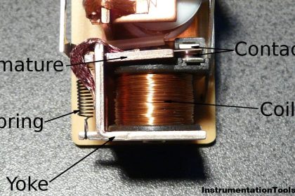
  • The Belt Sway Switch of is constructed with high reliability microswitches, lubricateless ball bearings, a touch roller which is titled to 75 , and other parts; its functions are designed with a large margin for sure action and long life

Application

The Belt Sway Switch functions in detecting any deviation or sway in the conveyor belt and providing an auto-alarm and sending out signal to stop the conveyor to avoid the damage to the conveyor belt and prevent scatter of conveyed materials because of the belt distortion.

Belt Sway Switch Conveyor Belt

Image Credits : phisher-ct

The Belt Sway Switch is necessary in the safe conveying system, widely used in the belt deviation detection of the belt conveyor for coal, cement and building materials, mining, electricity, port, metallurgy and chemical industries.
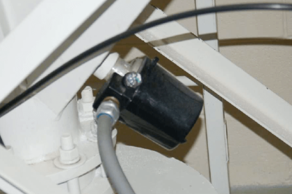
Installation

Belt Sway Switch Principle

Image Credits : phisher-ct

  • Prevention with slant on both sides of the switch should be installed on the conveyor maintenance channel, installation position should ensure that maintenance personnel in the event of an emergency operation is convenient
  • Switch is located in the conveyor belt on both sides, vertical roll with conveyor belt edge perpendicular to the plane, and on both sides of the conveyor belt is located at 1/3 height of vertical roll.
  • Switch and vertical roll conveyor belt normal position of the appropriate spacing is 50 ~ 100 mm.
  • Switch quantity should be according to the length of the conveyor, types and arrangement for sure. Should be in commonly conveyor head, tail, convex segmental arc, concave segment and location in the middle of the conveyor is set. (Note: when the conveyor is longer, the position in the middle of the conveyor can every 30~35 m set to 1)
  • The partial switch should through the mounting bracket and conveyor frame connection; switch bracket shall be installed on the conveyor and conveyor frame welding, after the completion of switch and switch bracket bolted

Source : phisher-ct

Don't Miss Our Updates
Be the first to get exclusive content straight to your email.
We promise not to spam you. You can unsubscribe at any time.
Invalid email address
You've successfully subscribed !

Continue Reading

Tilt Level Switch Working Principle
In-Line Flow Switch Working Principle and Animation
Side Mounting Float Switch Working Principle
Relay Principle & its Types
PLC Example with Switches
Thermal Dispersion Flow Switch Working Principle
Share This Article
Facebook Whatsapp Whatsapp LinkedIn Copy Link
Share
2 Comments
  • Yousef Shreim says:
    February 29, 2020 at 1:58 pm

    Good day,
    I am looking for Drift Switch with double pole, for conveyor belt

    Quantity 10 units

    Kindly let me know if you can quote.

    Reply
  • Duncan Leitch says:
    January 5, 2022 at 8:52 pm

    can you tell me the cost of a belt sway switch

    Reply

Leave a Reply Cancel reply

Your email address will not be published. Required fields are marked *

Stay Connected

128.3kFollowersLike
69.1kFollowersFollow
210kSubscribersSubscribe
38kFollowersFollow

Categories

Explore More

Flow Switch : What is it? – Applications
Switch Types and Common Terminology
Vibration Switch Working Principle
What is Contact bounce ?
Temperature Switch Principle
How Tilt Level Switch Works ?
What is a Limit Switch ?
Limit Switch Animation

Keep Learning

PLC Pressure Switch Ladder Diagram

Relays in Ladder Logic Tutorials

Process Switches Normal Status

Define Normal Status for each of the Process Switch

Switch NO or NC Contact

Normally-open and Normally-closed Switch Contacts

What is a Inductive Proximity Switch

What is a Inductive Proximity Switch ?

Proximity Switch PNP Type Working Animation

Proximity switches Circuit Diagram Operation

Float Level Switch Principle

Float Level Switch Working Principle Animation

Paddle switch Working Principle

Paddle Switch Working Principle

Magnetic Float Level Switch Working Animation

Learn More

level-transmitter-calibration-procedure

Level Transmitter Calibration Procedure

Piping and Instrumentation Diagram

What is Piping and Instrumentation Diagram (P&ID) ?

hard disk drive

Difference Between HDD and SSD

Single-element drum level control system

Single Element Drum Level Control System

Electrical Ground Loop

How to Solve Electrical Ground Loop Problems?

Digital Electronics Multiple Choice Questions

BCD Adder Objective Questions

Split range control scheme

Overview of Split Range Control

Calculate the Thermocouple’s Measurement Junction Temperature

Calculate the Thermocouple’s Measurement Junction Temperature

Menu

  • About
  • Privacy Policy
  • Copyright

Quick Links

  • Learn PLC
  • Helping Hand
  • Part Time Job

YouTube Subscribe

Follow US
All rights reserved. Reproduction in whole or in part without written permission is prohibited.
Welcome Back!

Sign in to your account

Username or Email Address
Password

Lost your password?