Inst ToolsInst ToolsInst Tools
  • Courses
  • Automation
    • PLC
    • Control System
    • Safety System
    • Communication
    • Fire & Gas System
  • Instrumentation
    • Design
    • Pressure
    • Temperature
    • Flow
    • Level
    • Vibration
    • Analyzer
    • Control Valve
    • Switch
    • Calibration
    • Erection & Commissioning
  • Interview
    • Instrumentation
    • Electrical
    • Electronics
    • Practical
  • Q&A
    • Instrumentation
    • Control System
    • Electrical
    • Electronics
    • Analog Electronics
    • Digital Electronics
    • Power Electronics
    • Microprocessor
  • Request
Search
  • Books
  • Software
  • Projects
  • Process
  • Tools
  • Basics
  • Formula
  • Power Plant
  • Root Cause Analysis
  • Electrical Basics
  • Animation
  • Standards
  • 4-20 mA Course
  • Siemens PLC Course
Reading: Upgrading the Electrical System in an Automobile
Share
Font ResizerAa
Inst ToolsInst Tools
Font ResizerAa
  • Courses
  • Design
  • PLC
  • Interview
  • Control System
Search
  • Courses
  • Automation
    • PLC
    • Control System
    • Safety System
    • Communication
    • Fire & Gas System
  • Instrumentation
    • Design
    • Pressure
    • Temperature
    • Flow
    • Level
    • Vibration
    • Analyzer
    • Control Valve
    • Switch
    • Calibration
    • Erection & Commissioning
  • Interview
    • Instrumentation
    • Electrical
    • Electronics
    • Practical
  • Q&A
    • Instrumentation
    • Control System
    • Electrical
    • Electronics
    • Analog Electronics
    • Digital Electronics
    • Power Electronics
    • Microprocessor
  • Request
Follow US
All rights reserved. Reproduction in whole or in part without written permission is prohibited.
Inst Tools > Blog > Practical Questions > Upgrading the Electrical System in an Automobile

Upgrading the Electrical System in an Automobile

A mechanic has an idea for upgrading the electrical system in an automobile originally designed for 6-volt operation.

Last updated: September 29, 2020 12:00 pm
Editorial Staff
Practical Questions
No Comments
Share
3 Min Read
SHARE

A mechanic has an idea for upgrading the electrical system in an automobile originally designed for 6-volt operation. He wants to upgrade the 6-volt headlights, starter motor, battery, etc, to 12 volts, but wishes to retain the original 6-volt generator and regulator.

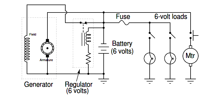
Shown here is the original 6-volt electrical system:

upgrading the electrical system in an automobile

The mechanic’s plan is to replace all the 6-volt loads with 12-volt loads, and use two 6-volt batteries connected in series, with the original (6-volt) regulator sensing the voltage across only one of those batteries:

upgrade the 6-volt headlights

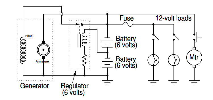
Explain how this system is supposed to work. Do you think the mechanic’s plan is practical, or are there any problems with it?

Answer:

So long as the generator is capable of outputting 12 volts, this system will work!

In this question, we see a foreshadowing of op-amp theory, with the regulator’s negative feedback applied to what is essentially a voltage divider (two equal-voltage batteries being charged by the generator).

The regulator circuit senses only 6 volts, but the generator outputs 12 volts. Fundamentally, the focus of this question is negative feedback and one of its many practical applications in electrical engineering.

This idea actually came from my father, who did this very thing on an International T-4 bulldozer. An important difference is that he used a single 12-volt battery rather than two 6-volt batteries, creating a center-tap connection on the 12-volt battery to make it perform as two 6-volt batteries.

To do this, he carefully drilled a hole in the top of the battery to intersect with the lead bus bar between the third and fourth cells, threading a screw into that bus bar as the center-tap terminal.

In fact, the entire motivation for this project was that it was far cheaper for him to get a new 12-volt battery than to buy a new 6-volt battery, and he had plenty of 12-volt electrical accessories (headlights, ignition coils, etc.) to upgrade the bulldozer.

One of the readers of my online textbook wished to do something similar, except his plan was to make the vehicle’s original 12-volt system output 24 volts so he could power surplus military accessories.

An important distinction for this fellow’s system is that he planned to have more than a few 12-volt loads remaining in the vehicle, such as a 12-volt radio:

Vehicle Electrical Batteries upgrade

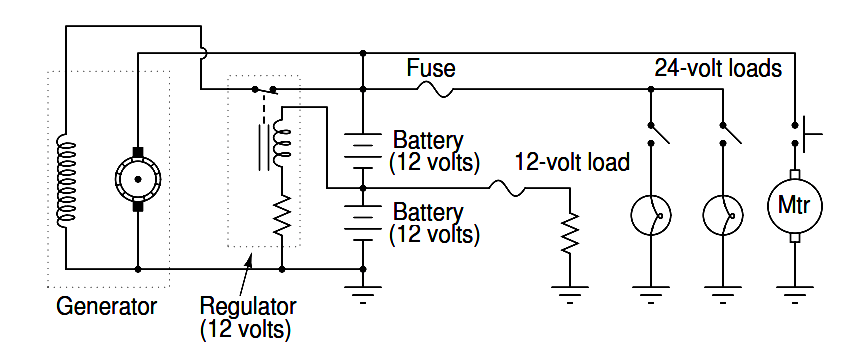
As a challenge for your students, ask them how well they think this system would work. It is a bit more complex than the system shown in the question, due to the two different load banks.

Don't Miss Our Updates
Be the first to get exclusive content straight to your email.
We promise not to spam you. You can unsubscribe at any time.
Invalid email address
You've successfully subscribed !

Continue Reading

Problem on Tachogenerator
Identify Faults in PID Control Loop
Programmable Logic Controller (PLC) Questions and Answers – 12
DP Transmitter Block and Bleed Valves
PLC Permissive for Motor Control
A Question on Steam Drum Water Level Measurement
Share This Article
Facebook Whatsapp Whatsapp LinkedIn Copy Link
Share
Leave a Comment

Leave a Reply Cancel reply

Your email address will not be published. Required fields are marked *

Stay Connected

128.3kFollowersLike
69.1kFollowersFollow
210kSubscribersSubscribe
38kFollowersFollow

Categories

Explore More

Pressure Switch Questions
pH Monitoring System Triggers an Alarm
Instrument Salesperson Question
Programmable Logic Controller (PLC) Questions and Answers – 8
Float-type Level Switch to Control a pump
Problem with Pirani Gauge
How a Bourdon Tube Pressure Gauge might be Adjusted for Linearity?
Questions on Dip Tube Type Level System

Keep Learning

Two Differential Pressure Transmitters

Pressure Level Transmitter Problems

Two pressure switches

Identify Two Pressure Switches Logic

Diagnosing the Electric Motor Circuit

Diagnosing Electric Motor Circuit

High and Low Ports on Pneumatic DP Transmitter

Identify High and Low Ports on Pneumatic DP Transmitter

three-phase motor control circuits

How Overload Heaters used to Automatically Shut the Motor OFF ?

DP transmitter Errors

DP Transmitter Calibration Errors

Determine the Pressure at Each Port of DP Transmitter

Determine the Pressure at Each Port of DP Transmitter

calibrating low-pressure instrument

Simulate Different Values for Pressure Instrument Under Test

Learn More

Demo of a SCADA Software – Level Control System

LVR Motor Controller Operation

Low Voltage Protection (LVP) and Low Voltage Release (LVR)

Case Statement in SCL Language

Case Statement in SCL Language

DeadWeight Tester

DeadWeight Tester Questions

Benefits of SIMOCODE over Intelligent MCC

Benefits of SIMOCODE over Intelligent MCC

Economics of Power Generation Objective Questions

100+ Economics of Power Generation Objective Questions and Answers

Control Room Design Guidelines

Control Room Design Guidelines

Electric Circuits Objective Questions

Electric Circuits Objective Questions – Set 17

Menu

  • About
  • Privacy Policy
  • Copyright

Quick Links

  • Learn PLC
  • Helping Hand
  • Part Time Job

YouTube Subscribe

Follow US
All rights reserved. Reproduction in whole or in part without written permission is prohibited.
Welcome Back!

Sign in to your account

Username or Email Address
Password

Lost your password?