This article discusses the PLC program for the Automatic Door Opener system using TIA Portal software. The system is designed to detect the presence of approaching humans or other objects, then automatically open the door to allow them through. After an object passes, the door will close again automatically. Apart from that, this system also has a feature that allows it to hold the door open.
Program Objective
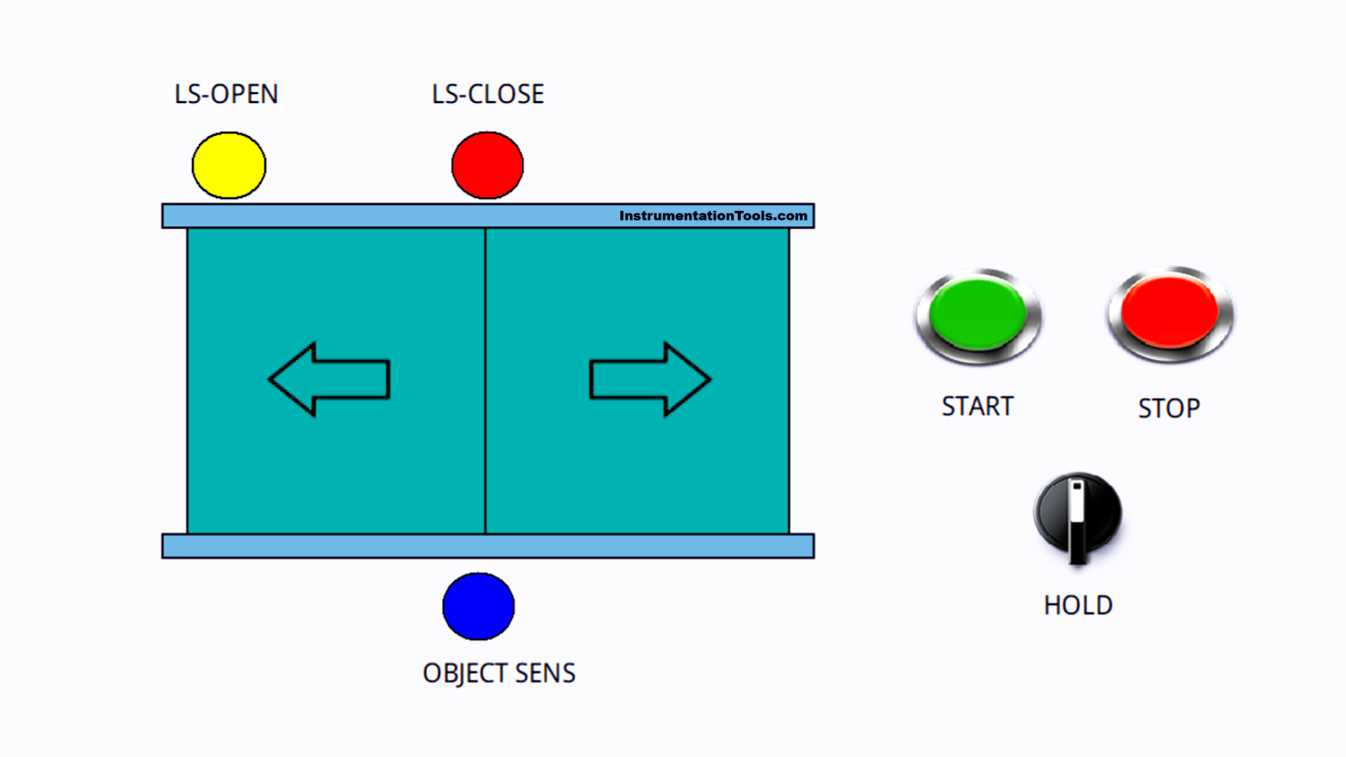
Automatic Door Opening System Steps:
- Initialization: System is ready to operate, door is closed.
- Detection: The sensor detects an approaching object.
- Open Door: The motor moves the door until it is fully opened.
- Hold: The door remains open briefly for 4 seconds.
- Close Door: The motor moves the door until it is fully closed.
- Hold Mode: The door will remain Open if the Selector Switch is set in “HOLD” mode.
- Repeat: Return to step 2 for the next detection.
This system has a sensor to detect objects and a limit switch to limit door opening/closing movements.
Automatic Door Opener Program
I/O Details
TIA Portal
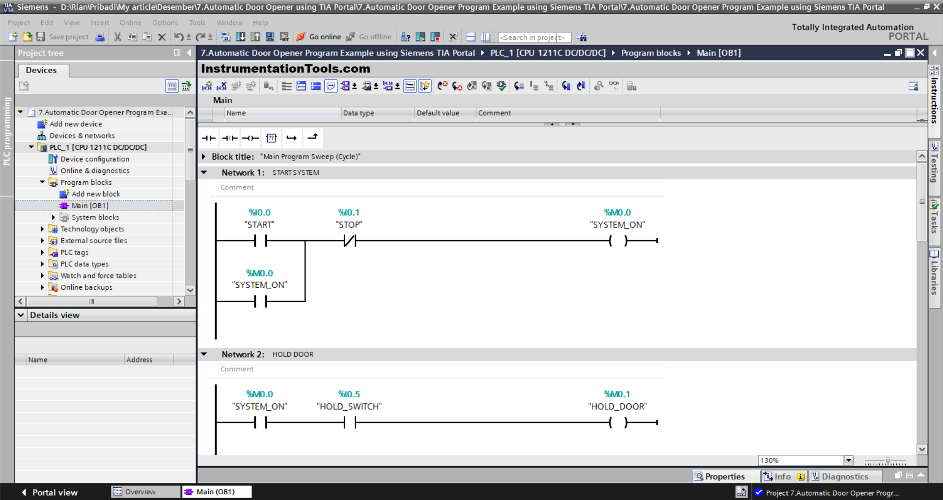
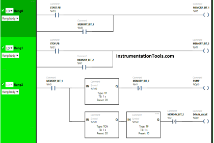
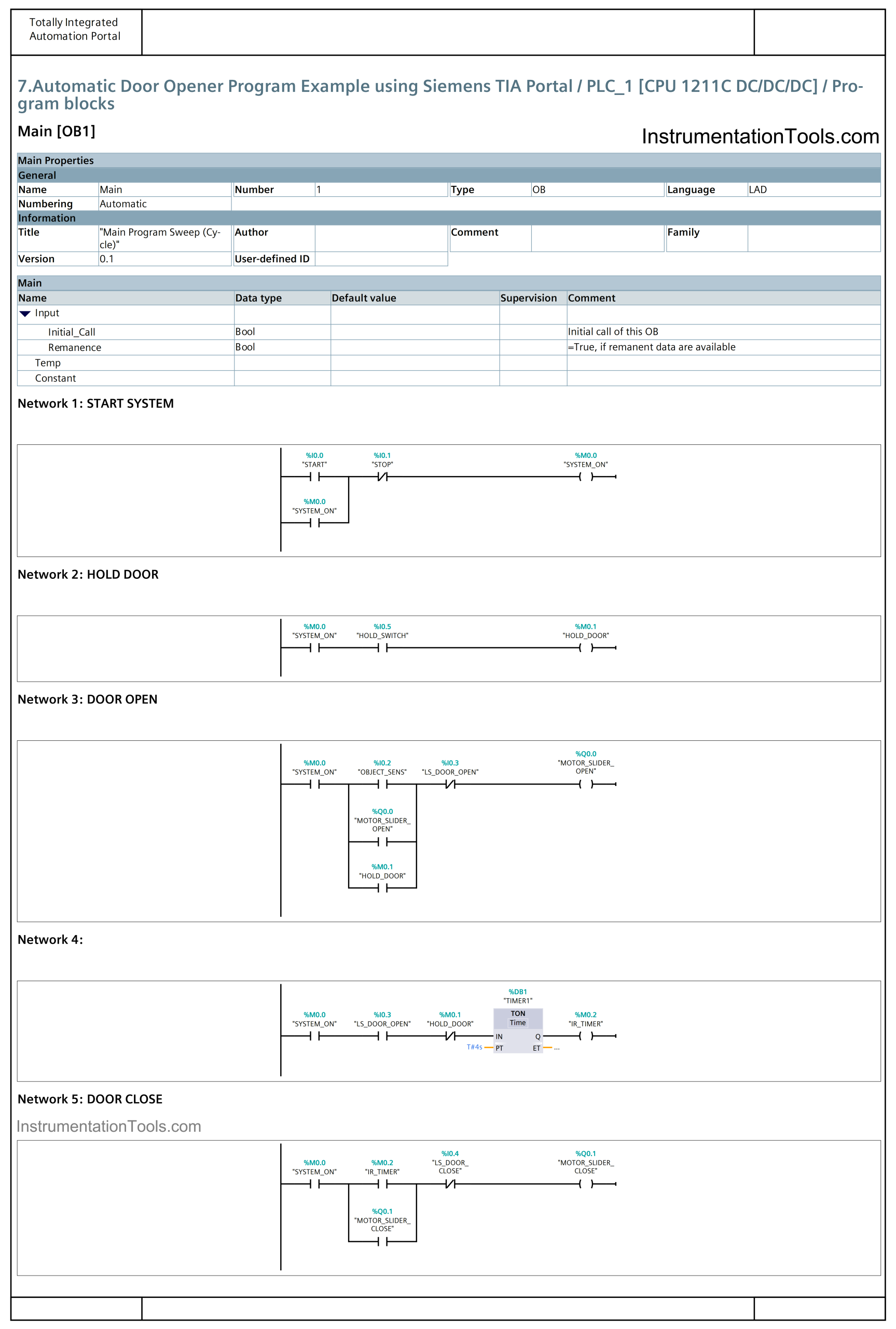
NETWORK 1 : (START SYSTEM)
In this network, when the START (I0.0) button is Pressed, the memory bit SYSTEM_ON (M0.0) will be in the HIGH state. Because it uses Latching, even though the START (I0.0) button has been released the memory bit SYSTEM_ON (M0.0) will remain in the HIGH state.
If the STOP (I0.1) button is Pressed, the memory bit SYSTEM_ON (M0.0) will be in the LOW state.
NETWORK 2 : (HOLD THE DOOR)
In this network, if the NO contact of the Selector Switch HOLD_SWITCH (I0.5) and the memory bit SYSTEM_ON (M0.0) are in the HIGH state, then the memory bit HOLD_DOOR (M0.1) will be in the HIGH state.
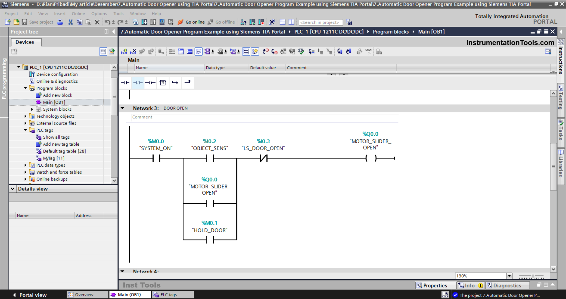
NETWORK 3 : (DOOR OPEN)
In this Network, the MOTOR_SLIDER_OPEN (Q0.0) output will be ON if the NO contact of the memory bit SYSTEM_ON (M0.0) and the sensor OBJECT_SENS (I0.2) are in the HIGH state. Because it uses Latching, the MOTOR_SLIDER_OPEN (Q0.0) output will remain in the ON state even though the NO contact of the sensor OBJECT_SENS (I0.2) is in the LOW state.
Or, the MOTOR_SLIDER_OPEN (Q0.0) output will be ON if the NO contact of the memory bit HOLD_DOOR (M0.1) is in the HIGH state.
The MOTOR_SLIDER_OPEN (Q0.0) output will be OFF when the NC contact of the Limit Switch LS_DOOR_OPEN (I0.3) is in the HIGH state.
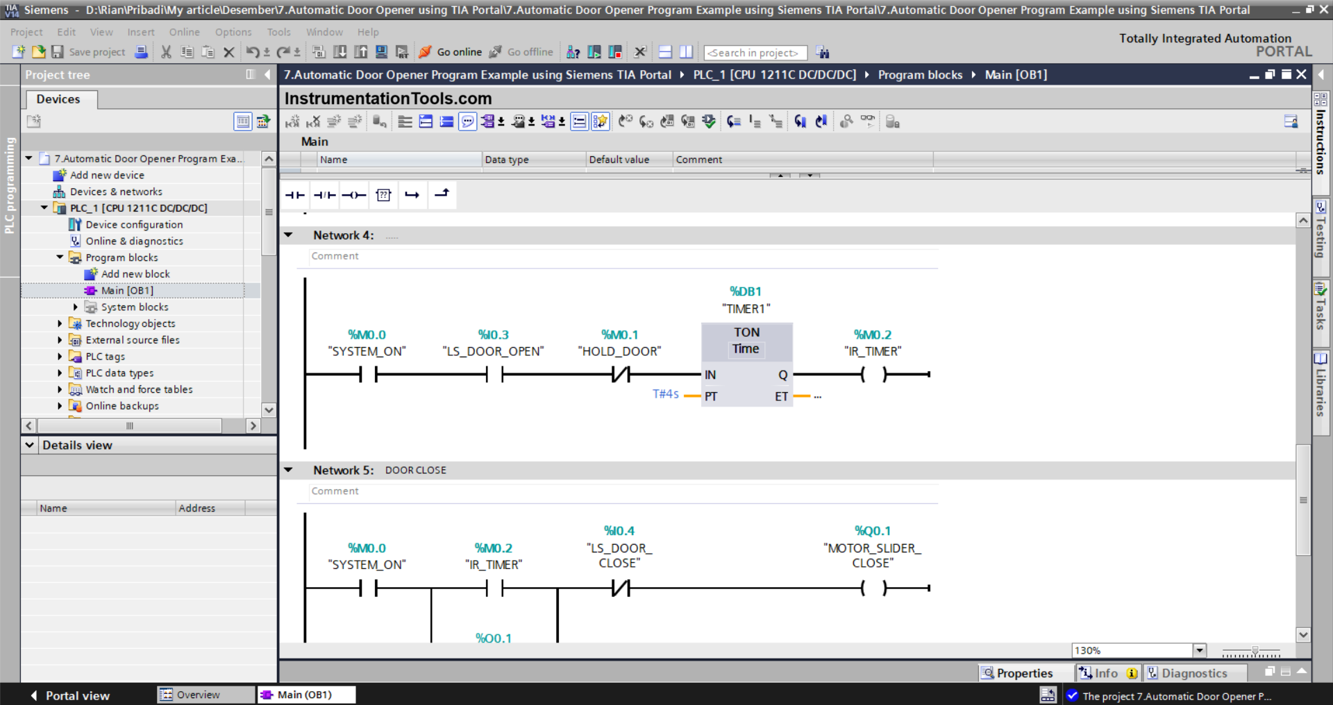
NETWORKS 4
The TIMER_OPEN (DB1) timer will start counting when the NO contact of the memory bit SYSTEM_ON (M0.0) and the Limit Switch LS_DOOR_OPEN (I0.3) are in the HIGH state. The timer TIMER_OPEN (DB1) will count to 4 seconds.
When the timer TIMER_OPEN (DB1) has finished counting, the memory bit IR_TIMER (M0.2) will be in the HIGH state.
If the NC contact of the memory bit HOLD_DOOR (M0.1) is in the HIGH state, then the timer TIMER_OPEN (DB1) will be reset.
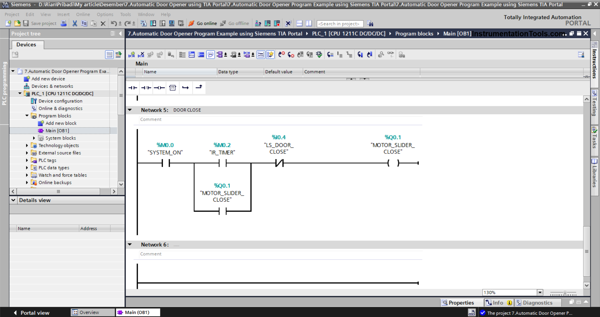
NETWORK 5 (DOOR CLOSE)
The MOTOR_SLIDER_CLOSE (Q0.1) output will be ON when the NO contacts of the memory bits SYSTEM_ON (M0.0) and IR_TIMER (M0.2) are in the HIGH state. Because it uses Latching, the MOTOR_SLIDER_CLOSE (Q0.1) output will remain in the ON state even though the NO contact of the memory bit IR_TIMER (M0.2) is in the LOW state.
When the NC contact of the Limit Switch LS_DOOR_CLOSE (Q0.1) is in the HIGH state, the MOTOR_SLIDER_CLOSE (Q0.1) output will be OFF.
Read Next:
- Edge Detection in PLC Programming
- Siemens LOGO PLC Programming Course
- D Flip Flop PLC Ladder Logic Explained
- Why is 24 Volts Commonly used in PLC?
- Electrical Panel Door Earth Bonding