Inst ToolsInst ToolsInst Tools
  • Courses
  • Automation
    • PLC
    • Control System
    • Safety System
    • Communication
    • Fire & Gas System
  • Instrumentation
    • Design
    • Pressure
    • Temperature
    • Flow
    • Level
    • Vibration
    • Analyzer
    • Control Valve
    • Switch
    • Calibration
    • Erection & Commissioning
  • Interview
    • Instrumentation
    • Electrical
    • Electronics
    • Practical
  • Q&A
    • Instrumentation
    • Control System
    • Electrical
    • Electronics
    • Analog Electronics
    • Digital Electronics
    • Power Electronics
    • Microprocessor
  • Request
Search
  • Books
  • Software
  • Projects
  • Process
  • Tools
  • Basics
  • Formula
  • Power Plant
  • Root Cause Analysis
  • Electrical Basics
  • Animation
  • Standards
  • 4-20 mA Course
  • Siemens PLC Course
Reading: As-found and As-left Documentation during Calibration
Share
Font ResizerAa
Inst ToolsInst Tools
Font ResizerAa
  • Courses
  • Design
  • PLC
  • Interview
  • Control System
Search
  • Courses
  • Automation
    • PLC
    • Control System
    • Safety System
    • Communication
    • Fire & Gas System
  • Instrumentation
    • Design
    • Pressure
    • Temperature
    • Flow
    • Level
    • Vibration
    • Analyzer
    • Control Valve
    • Switch
    • Calibration
    • Erection & Commissioning
  • Interview
    • Instrumentation
    • Electrical
    • Electronics
    • Practical
  • Q&A
    • Instrumentation
    • Control System
    • Electrical
    • Electronics
    • Analog Electronics
    • Digital Electronics
    • Power Electronics
    • Microprocessor
  • Request
Follow US
All rights reserved. Reproduction in whole or in part without written permission is prohibited.
Inst Tools > Blog > Calibration > As-found and As-left Documentation during Calibration

As-found and As-left Documentation during Calibration

Last updated: November 15, 2019 3:24 pm
Editorial Staff
Calibration
2 Comments
Share
4 Min Read
SHARE

As-found and as-left Documentation during Calibration

Calibration is the comparison of a measurement device (an unknown) against an equal or better standard. A standard in a measurement is considered the reference; it is the one in the comparison taken to be the more correct of the two. Calibration finds out how far the unknown is from the standard.

A “typical” commercial calibration uses the manufacturer’s calibration procedure and is performed with a reference standard at least four times more accurate than the instrument under test.

An important principle in calibration practice is to document every instrument’s calibration as it was found and as it was left after adjustments were made. The purpose for documenting both conditions is to make data available for calculating instrument drift over time. If only one of these conditions is documented during each calibration event, it will be difficult to determine how well an instrument is holding its calibration over long periods of time.

Excessive drift is often an indicator of impending failure, which is vital for any program of predictive maintenance or quality control. Typically, the format for documenting both As-Found and As-Left data is a simple table showing the points of calibration, the ideal instrument responses, the actual instrument responses, and the calculated error at each point.

Also Read : Instrument Zero and Span Calibration

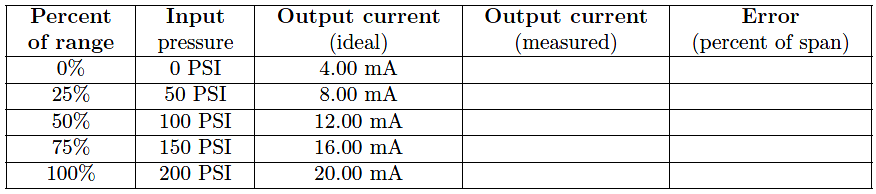
The following table is an example for a pressure transmitter with a range of 0 to 200 PSI over a five-point scale:

As-found and as-left documentation

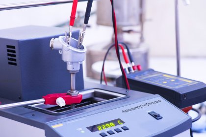
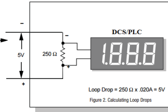
The following photograph shows a single-point “As-Found” calibration report on a temperature indicating controller, showing the temperature of the calibration standard (−78.112 degrees Celsius), the display of the instrument under test (IUT, −79 degrees Celsius), and the error between the two (−0.888 degrees Celsius):

Instrument Calibration Record

Note that the mathematical sign of the error is important. An instrument that registers −79 degrees when it should register −78.112 degrees exhibits a negative error, since its response is lower (i.e. more negative) than it should be.

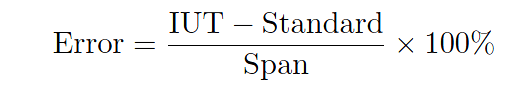
Expressed mathematically: Error = IUT − Standard. When the error must be expressed in percentage of span, the formula becomes:

Instrument Calibration Error Formula

Calibration Terms

As found data : The reading of the instrument before it is adjusted.

As left data : The reading of the instrument after adjustment or “same as found,” if no adjustment was made.

Optimization : Adjusting a measuring instrument to make it more accurate is NOT part of a typical calibration and is frequently referred to as “optimizing” or “nominalizing” an instrument.

Out-of-tolerance (OOT) condition : When an instrument’s performance is outside its specifications, it is considered an outof- tolerance (OOT) condition, resulting in the need to adjust the instrument back into specification.

Limited calibration : It may be more cost effective to have a limited calibration when only certain functions of an instrument are not utilized by the user.

Test uncertainty ratio (TUR) : This is the ratio of the accuracy of the instrument under test compared to the accuracy of the reference standard.

Verification : Typically referring to a functional check or performing a comparison with an instrument not classified as a reference standard for the full measurement.

Measurement Uncertainty : Influences in the measurement causing uncertainty (%). Examples: temp., pressure., humidity, fittings etc.

MPE – Maximum Permissible Error  : Tolerance allowed in process by the customer for determining whether or not an instrument passes or fails (instrument & process tolerance)

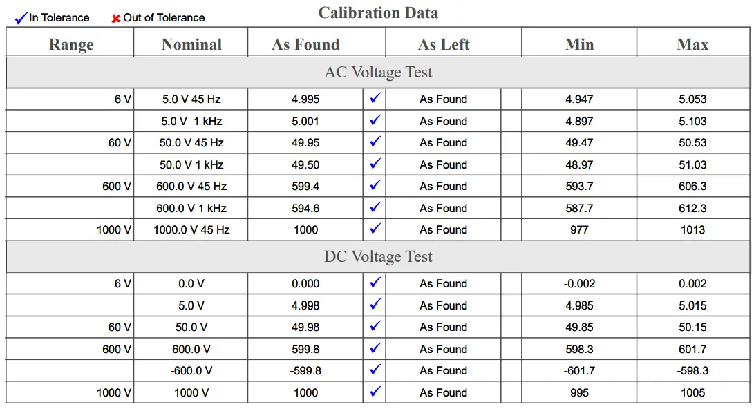
Example Calibration Record Sheet :

As-found and As-left Calibration

Credits : by Tony R. Kuphaldt – under Creative Commons Attribution 4.0 License

Don't Miss Our Updates
Be the first to get exclusive content straight to your email.
We promise not to spam you. You can unsubscribe at any time.
Invalid email address
You've successfully subscribed !

Continue Reading

How-to do Control Valve Calibration?
Smart Transmitter Calibration Tutorial Part 2
Uncertainty Calculations of Pressure Calibration
Hierarchy of Calibration Organizations
Displacer (buoyancy) Level Transmitter Principle, Limitations, Design, Installation & Calibration
Closed tank DP Level Transmitter with wet leg elevation zero remote mount Calibration
Share This Article
Facebook Whatsapp Whatsapp LinkedIn Copy Link
Share
2 Comments
  • DEC says:
    August 26, 2021 at 8:38 pm

    In the above Error for the temperature transmitter, that is not the % of Span error, only the difference between the IUT & Standard readings.

    Reply
  • Hery Purwanto says:
    July 31, 2023 at 8:44 am

    this is very good can you give me calibration procedure and record data such as flow transmitter instrument, pressure transmitter, level transmitter, DP transmitter, analyzer, sensor, selenoid Valve, MOV penstock

    Reply

Leave a Reply Cancel reply

Your email address will not be published. Required fields are marked *

Stay Connected

128.3kFollowersLike
69.1kFollowersFollow
210kSubscribersSubscribe
38kFollowersFollow

Categories

Explore More

Importance of Unit Measurement
Pressure Safety Valves Functional Testing
Multimeter – What Do Digits and Counts Mean?
Smart Transmitter Calibration Tutorial Part 3
Multiphase Flow Meter Calibration Procedure
Functional Testing of Control Valve Positioners
Different Types of Temperature Calibrators
Calibration : Up-tests and Down-tests

Keep Learning

Step by step guide for Gas Flow Meter Calibration

Step by Step Guide for Gas Flow Meter Calibration

ORP-sensor-calibration

Oxidation-Reduction Potential (ORP) Sensor Calibration Procedure

Temperature Switch Calibration

How to Calibrate Temperature Switch? – Instrument Basics

Pressure Gauge Calibration Procedure

Comparison of Accuracy and Precision

Difference between Accuracy and Precision

level-transmitter-calibration-procedure

Level Transmitter Calibration Procedure

Common Mistakes in Dead Weight Tester

Common Mistakes to Avoid When Using Dead Weight Tester

History of Measurement

History of Measurement

Learn More

Transmitter Identification Codes

Instrument Identification Tags

Rupture Disc

Rupture Discs bursts caused too many Urea Plant Shutdowns

Single Phase Earth Return System

Single Phase Earth Return System Advantages & Disadvantages

PLC Program to Operate Stamping of Parts

PLC Application for Stamping Operation – Example Programming

Thermocouples

Thermocouples

Spring Loaded Variable Area Flowmeter Working Principle

Spring Loaded Variable Area Flow Meter Working Principle

Smoke Detection System Questions

Interview Questions on Smoke Detection System

Remote Diaphragm Seal Transmitter for Vacuum Application

Remote Diaphragm Seal Transmitter for Vacuum Application

Menu

  • About
  • Privacy Policy
  • Copyright

Quick Links

  • Learn PLC
  • Helping Hand
  • Part Time Job

YouTube Subscribe

Follow US
All rights reserved. Reproduction in whole or in part without written permission is prohibited.
Welcome Back!

Sign in to your account

Username or Email Address
Password

Lost your password?