Inst ToolsInst ToolsInst Tools
  • Courses
  • Videos
  • Q & A
    • Interview
      • Instrumentation
      • Electronics
      • Electrical
      • Practical Questions
    • MCQ
      • Instrumentation MCQ
      • Electrical MCQ
      • Electronics MCQ
      • Control Systems MCQ
      • Analog Electronics MCQ
      • Digital Electronics MCQ
      • Power Electronics MCQ
      • Microprocessor MCQ
      • Multiple Choice Questions
  • EE
    • Electronics
      • Electronics Q & A
      • Electronic Basics
      • Electronic Devices & Circuits
      • Electronics Animation
      • Digital Electronics
    • Electrical
      • Electrical Basics
      • Electrical Q & A
      • Power Electronics
      • Electrical Machines
      • Electrical Animation
      • Power Systems
      • Switchgear & Protection
      • Transmission & Distribution
  • Measure
    • Control Valves
    • Calibration
    • Temperature
    • Pressure
    • Flow
    • Level
    • Analyzers
    • Switches
    • Vibration
    • Solenoid Valve
  • Control
    • PLC Tutorials
    • Control Systems
    • Safety Instrumented System (SIS)
    • Communication
    • Fire & Gas System
  • More
    • Design
    • Tools
    • Animation
    • Basics
    • Formulas
    • Standards
    • TextBooks
    • Common
    • Software
    • Excel Tools
    • Erection & Commissioning
    • Process Fundamentals
    • Videos
    • Books
Search
All rights reserved. Reproduction in whole or in part without written permission is prohibited.
Reading: How to Analyze a Cascade Control Loop?
Share
Notification Show More
Font ResizerAa
Inst ToolsInst Tools
Font ResizerAa
  • Courses
  • PLC Tutorials
  • Control Systems
Search
  • Courses
  • Videos
  • Q & A
    • Interview
    • MCQ
  • EE
    • Electronics
    • Electrical
  • Measure
    • Control Valves
    • Calibration
    • Temperature
    • Pressure
    • Flow
    • Level
    • Analyzers
    • Switches
    • Vibration
    • Solenoid Valve
  • Control
    • PLC Tutorials
    • Control Systems
    • Safety Instrumented System (SIS)
    • Communication
    • Fire & Gas System
  • More
    • Design
    • Tools
    • Animation
    • Basics
    • Formulas
    • Standards
    • TextBooks
    • Common
    • Software
    • Excel Tools
    • Erection & Commissioning
    • Process Fundamentals
    • Videos
    • Books
Follow US
All rights reserved. Reproduction in whole or in part without written permission is prohibited.
Inst Tools > Blog > Control Systems > How to Analyze a Cascade Control Loop?

How to Analyze a Cascade Control Loop?

Last updated: October 25, 2019 11:25 am
Editorial Staff
Control Systems
No Comments
Share
3 Min Read
SHARE

Let us discuss a steam-heated reactor control system with a cascade strategy, where the temperature controller drives a setpoint signal to a “slave” steam flow controller:

Cascade Control Loop

cascade temperature controller

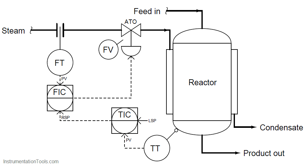
In order to determine the proper actions for each controller in this system, it is wise to begin with the slave controller (FIC), since the master controller (TIC) depends on the slave controller being properly configured in order to do its job properly. Just as we would first tune the slave controller in a cascade system prior to tuning the master controller, we should first determine the correct action for the slave controller prior to determining the correct action for the master controller.

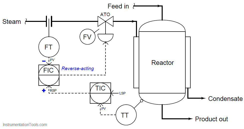
Once again we may apply a “thought experiment” to this system in order to choose the appropriate slave controller action. If we imagine the steam flow rate suddenly increasing, we know we need the control valve to close off in order to counter-act this change. Since the valve is still air-to-open, this requires a decrease in the output signal from the FIC. Thus, the FIC must be reverse-acting. We shall denote this with a “−” label next to the process variable (PV) input, and a “+” label next to the remote setpoint (RSP) input:

cascade temperature controller - 1

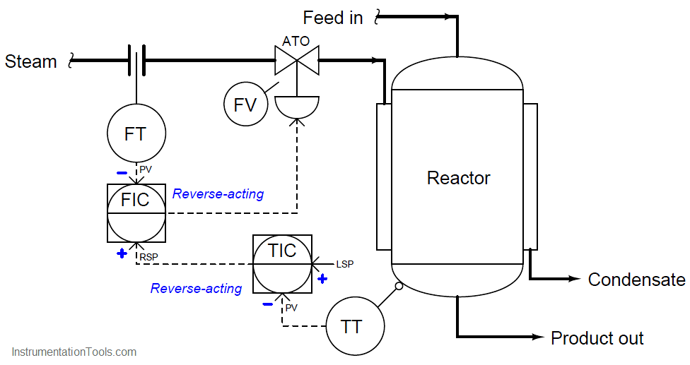
Now that we know the slave controller must be reverse-acting, we may choose the action of the master controller. Applying another “thought experiment” to this system, we may imagine the reactor temperature suddenly increasing. If this were to happen, we know we would need the control valve to close off in order to counter-act this change: sending less steam to a reactor that is getting too hot.

Since the valve is air-to-open, this requires a decrease in the output signal from the FIC. Following the signal path backwards from the control valve to the FIC to the TIC, we can see that the TIC must output a decreasing signal to the FIC, calling for less steam flow.

A decreasing output signal at the TIC enters the FIC’s noninverting (“+”) input, causing the FIC output signal to also decrease. Thus, we need the TIC to be reverse-acting as well. We shall denote this with a “−” label next to the process variable (PV) input, and a “+” label next to the local setpoint (LSP) input:

cascade temperature controller - 2

With these unambiguous labels in place at each controller’s inputs, we are well-prepared to qualitatively analyze the response of this cascade control system to process upsets, to instrument failure scenarios, or to any other change.

No longer will we be led astray by the singular label of “reverse-acting”, but instead will properly recognize the different directions of action associated with each input signal to each controller.

Also Read : Feedforward Control

Don't Miss Our Updates
Be the first to get exclusive content straight to your email.
We promise not to spam you. You can unsubscribe at any time.
Invalid email address
You've successfully subscribed !

Recommended Articles

Problem on Pressure and Level Control Loops
PLC Alarm and Trip Documentation
Motor Control Signal Interface
Difference between Feedback, Feedforward, and Cascade Control?
What is PCS 7?
What is the BACNet Protocol? BACNet IP vs. BACNet MS/TP
Share This Article
Facebook Whatsapp Whatsapp LinkedIn Copy Link
Share
Leave a Comment

Leave a Reply Cancel reply

Your email address will not be published. Required fields are marked *

Stay Connected

128.3kFollowersLike
69.1kFollowersFollow
208kSubscribersSubscribe
38kFollowersFollow

Categories

Recent Comments

  • William Snyder on Top Non-PLC Certification Courses for Automation Professionals
  • Kamli on Top Free PLC Software
  • Guifty Shimica on Top Non-PLC Certification Courses for Automation Professionals
  • Guifty Shimica on Top Non-PLC Certification Courses for Automation Professionals

Related Articles

PID Loop Tuning

PID Controller Loop Tuning Questions and Answers – Part 1

Comparison of Proportional Integral Derivative Controllers (PID)

Comparison of Proportional Integral Derivative Controllers (PID)

Alarm annunciator circuit with acknowledge

Alarm Annunciator Circuit with Acknowledge

Proportional Band example

Why Offset in Proportional Controller ?

Library of PlantPAx Process Objects

How to Download PlantPAx Library?

Instrumentation Logic Checks

How to Do Logic Checks During Plant Pre-Commissioning

Distributed Control System Interview Questions

Comparison of Control Loops - Open, Closed, Cascade, Feedforward, Ratio

Comparison of Control Loops – Open, Closed, Cascade, Feedforward, Ratio

More Articles

What is Pump Redundancy

What is Pump Redundancy?

SWAS Analyzer Questions

SWAS Analyzers Questions and Answers

Stepper Motor Parts

Stepper Motor MCQ

D’Arsonval Movement

D’Arsonval Movement

PLC Boxes Sorting Based on Height

PLC Programming: Sorting and Distribution of Boxes by Height

How to Filter Digital and Analog Inputs in a PLC

How to Filter Digital and Analog Inputs in a PLC?

Limit, Selector, and Override controls

Limit, Selector, and Override controls

Thermocouple cold junction compensation

Why Thermocouple Reference Junction Compensation Required ?

Follow US
All rights reserved. Reproduction in whole or in part without written permission is prohibited.
Welcome Back!

Sign in to your account

Username or Email Address
Password

Lost your password?