This article discusses the use of Analog Output in the Mitsubishi FX3U PLC. The analog output on a PLC is a voltage (0–10V) or current (4–20mA) signal used to control external devices such as inverter motors, actuators, or analog indicators. The Mitsubishi FX3U Lollete PLC features a 12-bit resolution (0–4095), meaning this digital value is converted by the analog output module into a physical voltage or current signal based on the configuration. In this program, testing was conducted by manually adjusting the output value and observing the resulting voltage within the 0 to 10-volt range to ensure proper conversion and control performance.
Program Objective
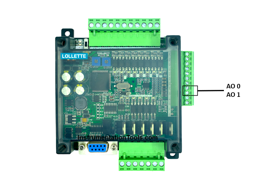
The PLC converts digital data with 12-bit resolution (0-4095) into physical voltage signals (0-10V) through a process called Digital-to-Analog Conversion (DAC). DAC is the conversion process of digital signals (binary or numerical values) generated by the PLC into continuous analog signals, such as voltage or current. In the Mitsubishi FX3U Lolette PLC, there are two Analog Output (AO 0 and AO 1) addresses available, both of which can only produce 0-10V voltage signals.
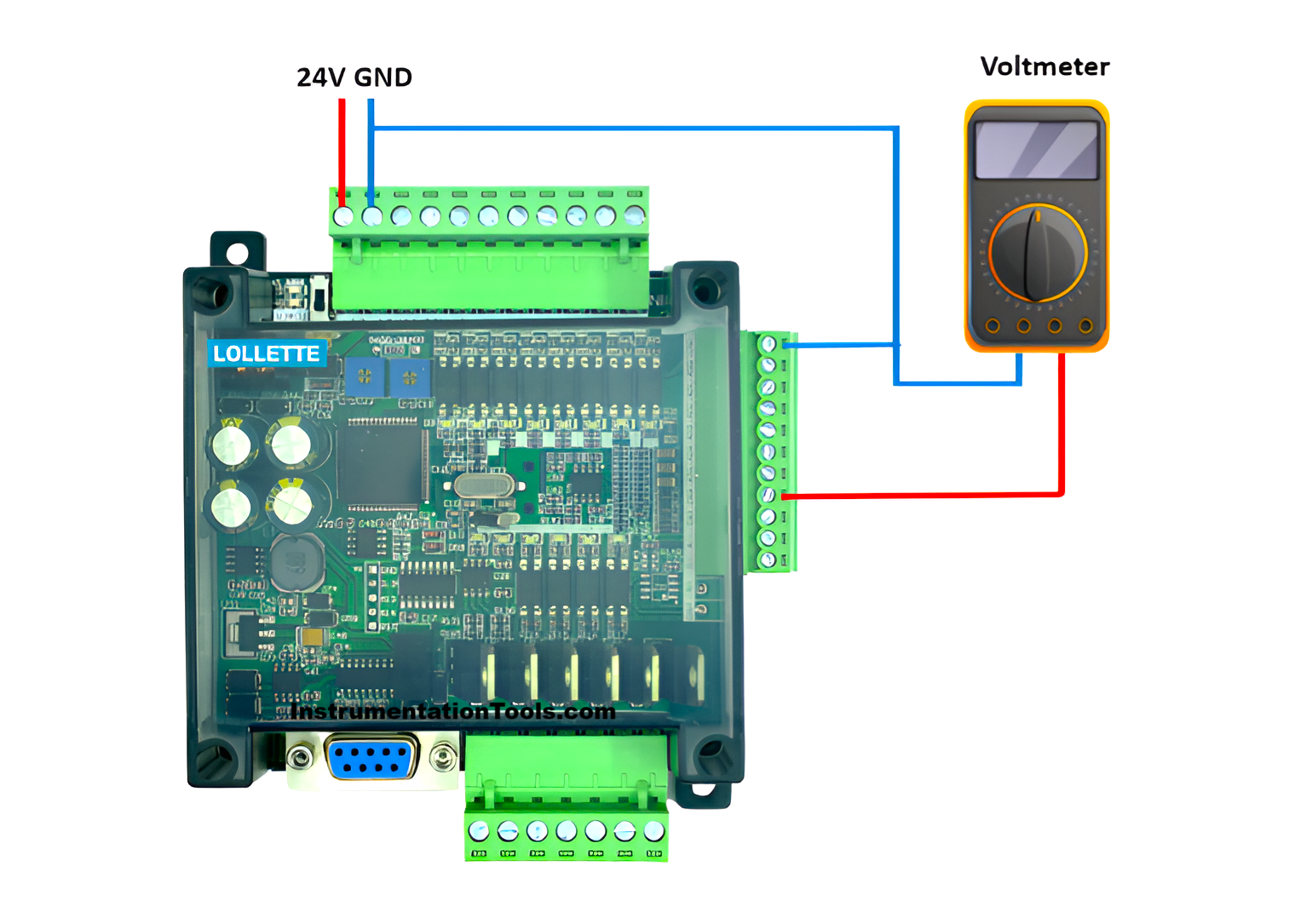
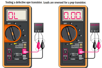
To determine the analog output value generated by the PLC, an avometer or voltmeter is used to measure the DC voltage produced at the Analog Output 0 terminal.
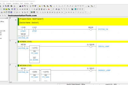
Mitsubishi Analog Output Ladder Logic
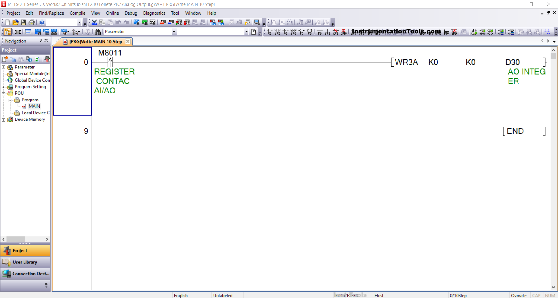
RUNG 0
In this rung, the NO contact from REGISTER CONTACT AI/AO (M8011) is used as a trigger to activate the WR3A instruction, which is a special instruction for setting the analog output value on the PLC.
The value K0 indicates the address of the analog output module being used, while K0 refers to the selected output port, namely DA0.
The resolution value for the analog output is defined through data memory word D30 (AO INTEGER), which contains a number in the range of 0–4095 (12-bit resolution).
When the WR3A instruction is executed, the digital value will be converted into an analog voltage signal of 0–10V, which will be output through port DA0.
Simulation Video
In the video below, we simulated the program with real hardware and results displayed.
Read Next:
- How does a PLC do the Scaling for a Sensor?
- Studio 5000 and FactoryTalk View Studio Logic
- Ladder Logic for Sensor Scaling with Offset
- Analog Input in Mitsubishi FX3U LOLLETTE PLC
- Water Pump PLC Program using CX-Programmer