This article discusses the control of analog output on the Mitsubishi FX3U-14MT PLC using Weintek HMI software EasyBuilder Pro. EasyBuilder Pro features an Online Simulation function, which allows users to test the HMI interface directly connected to the PLC via a computer, without requiring a physical HMI device. In the analog output setup, the digital resolution value (0–4095) is provided through input parameters designed on the HMI interface in EasyBuilder Pro. This value is then sent to the PLC to be converted into a 0–10V voltage signal.
Required Devices
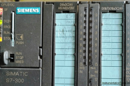
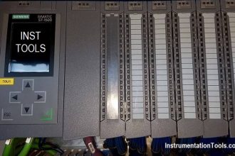
1. PLC FX3U-14MT Lollette
This Mitsubishi PLC features 8 digital inputs, 6 transistor outputs, 3 analog inputs, and 3 analog outputs. It operates with a 24V DC power supply and uses an RS232 DB9 port (38.4 Kbps). It is suitable for learning purposes and small projects, but less ideal for large-scale industrial applications.
2. EasyBuilder Pro Software
The EasyBuilder Pro software is used to design HMI displays on Weintek devices. It supports communication with PLCs and includes offline/online simulation features without the need for physical HMI hardware.
3. GX Works2 Software
The GX Works2 is the official software from Mitsubishi for programming MELSEC series PLCs such as FX3U and FX5U. It is used to create, edit, and monitor PLC programs.
4. USB to Serial RS232 Cable
An adapter that converts a USB port into an RS232 port, enabling modern computers to connect with industrial devices that still use serial communication.
How to do an online simulation of PLC FX3U-14MT with EasyBuilder Pro
Provide the PLC with a 24 VDC power supply.
Connect the PLC to the PC using a USB to Serial RS232 cable.
PLC Program
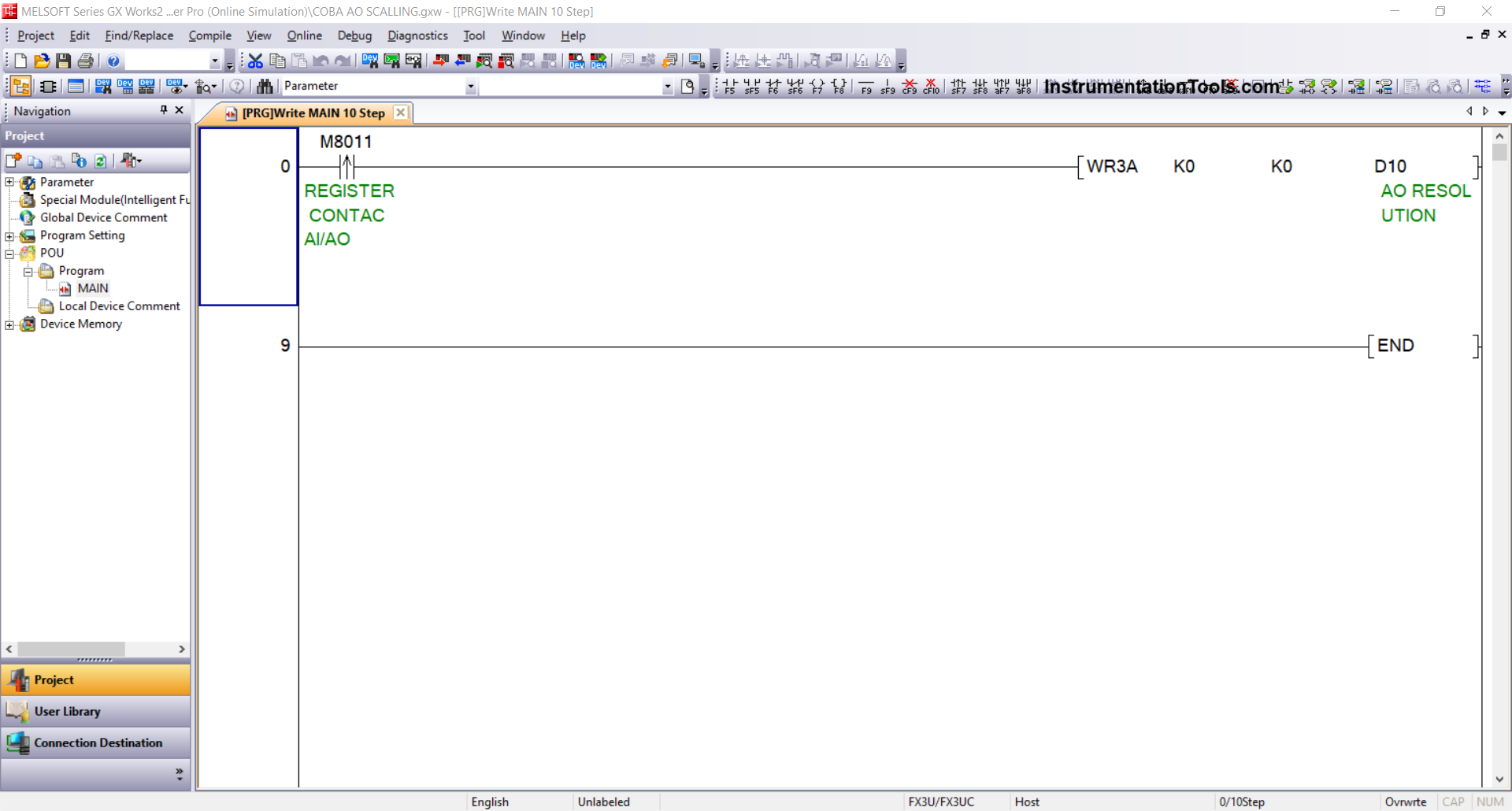
1. Open GX Works2 Mitsubishi PLC software and create the PLC Program.
Use the WR3A instruction with module setting “0/K0” and Analog Output address “0/K0”. Memory word AO RESOLUTION (D10) is used to store the analog output resolution data.
2. Check Device Connection
Check the USB to Serial RS-232 adapter connection via Device Manager. For example, it is detected on COM5 with the following settings:
- Bit rate: 38.4 Kbps
- Data bits: 7
- Parity: Even
- Stop bits: 1
3. Set Connection Parameters
In the software, go to Connection Detection → Connection1, then:
- Select Interface: Serial USB (RS-232C)
- COM Port: COM5
- Transmission Speed: 38.4 Kbps
- Setup: Parity Even, Data bits 7, Stop bits 1
- Click Connection Test. If successful, the message “Successfully Connected with the FX3U/FX3UC CPU” will appear.
4. Upload the Program to the PLC
Click the Online menu → Write to PLC, select Parameter + Program, then press Execute.
Create Design and Simulation of HMI with EasyBuilder Pro for FX3U PLC
1. Create a New Project
Open EasyBuilder Pro → click New, select the type of HMI used, then click OK.
2. Add PLC Device
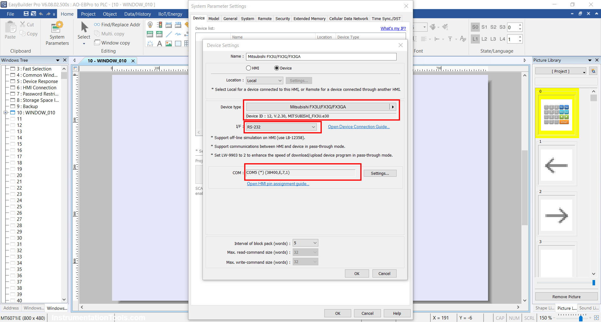
In the System Parameter window, click New Device/Server, then set:
- Port: RS-232
- COM: COM5(*)(38400,E,7,1)
- Device Type: Mitsubishi FX3U/FX3G/FX3GA
- Click OK.
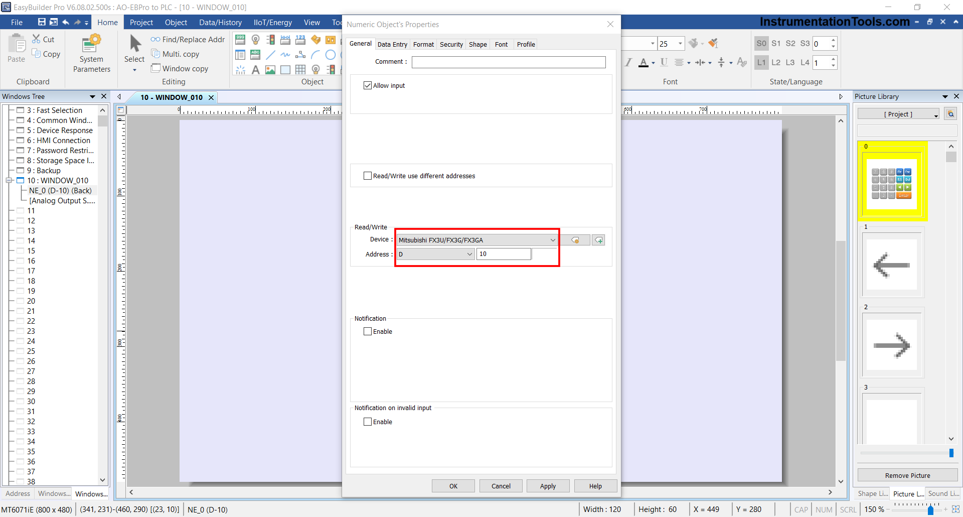
3. Design the HMI Interface
Insert “Numeric Object” → set the Device to “Mitsubishi FX3U/FX3G/FX3A” and the memory word address to “D10”, according to the Analog Output Resolution address in the PLC.
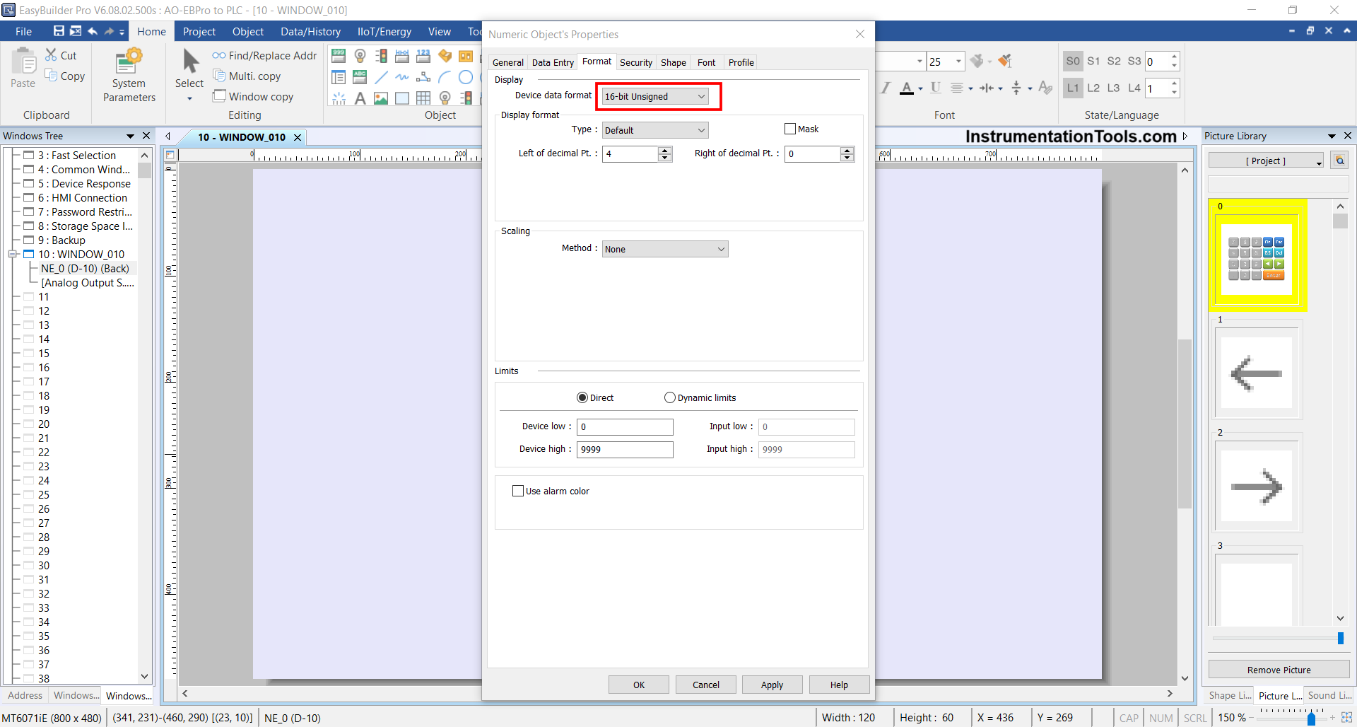
Set Data Format to “16-bit Unsigned”, then click OK.
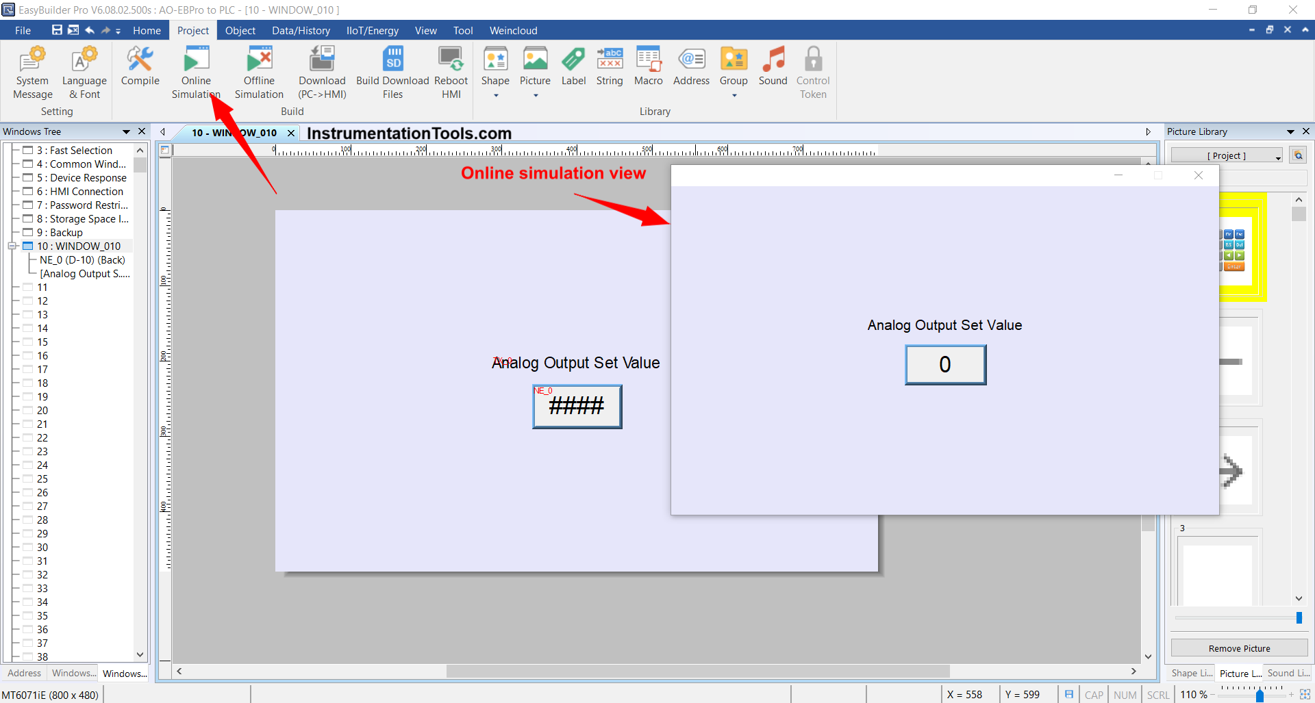
4. To test, click Project → Online Simulation.
5. Run the Simulation
If the connection is successful, the simulation display will appear, and the HMI will be connected to the PLC.
Note: If the message “Device Not Responding” appears, it means the connection failed. Try changing the Device Type in System Parameter to FX0S/FX0N/FX1S/FX1N/FX2/FX3SA, because the FX3U-14MT model (Lollette) sometimes is not fully compatible with the FX3U type in EasyBuilder Pro.
Testing Video
In the video below, we tested the analog output in the Mitsubishi PLC with Weintek EasyBuilder Pro HMI software.
Read Next:
- EasyBuilder Pro Simulation of Mitsubishi PLC
- Ladder Logic for Parking Garage Indicator System
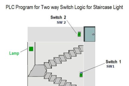
- PLC Programming for Electrical Stairway Lighting
- Analog Input in Mitsubishi FX3U LOLLETTE PLC
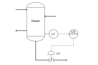
- Demo of Level Control SCADA System Software