Inst ToolsInst ToolsInst Tools
  • Courses
  • Automation
    • PLC
    • Control System
    • Safety System
    • Communication
    • Fire & Gas System
  • Instrumentation
    • Design
    • Pressure
    • Temperature
    • Flow
    • Level
    • Vibration
    • Analyzer
    • Control Valve
    • Switch
    • Calibration
    • Erection & Commissioning
  • Interview
    • Instrumentation
    • Electrical
    • Electronics
    • Practical
  • Q&A
    • Instrumentation
    • Control System
    • Electrical
    • Electronics
    • Analog Electronics
    • Digital Electronics
    • Power Electronics
    • Microprocessor
  • Request
Search
  • Books
  • Software
  • Projects
  • Process
  • Tools
  • Basics
  • Formula
  • Power Plant
  • Root Cause Analysis
  • Electrical Basics
  • Animation
  • Standards
  • 4-20 mA Course
  • Siemens PLC Course
Reading: How to Use Analog Input in Mitsubishi FX3U LOLLETTE PLC?
Share
Font ResizerAa
Inst ToolsInst Tools
Font ResizerAa
  • Courses
  • Design
  • PLC
  • Interview
  • Control System
Search
  • Courses
  • Automation
    • PLC
    • Control System
    • Safety System
    • Communication
    • Fire & Gas System
  • Instrumentation
    • Design
    • Pressure
    • Temperature
    • Flow
    • Level
    • Vibration
    • Analyzer
    • Control Valve
    • Switch
    • Calibration
    • Erection & Commissioning
  • Interview
    • Instrumentation
    • Electrical
    • Electronics
    • Practical
  • Q&A
    • Instrumentation
    • Control System
    • Electrical
    • Electronics
    • Analog Electronics
    • Digital Electronics
    • Power Electronics
    • Microprocessor
  • Request
Follow US
All rights reserved. Reproduction in whole or in part without written permission is prohibited.
Inst Tools > Blog > PLC Tutorials > How to Use Analog Input in Mitsubishi FX3U LOLLETTE PLC?

How to Use Analog Input in Mitsubishi FX3U LOLLETTE PLC?

Learn about how to use Analog Input in Mitsubishi FX3U PLC hardware and how to work with 0–10 V and 4–20 mA signals.

Last updated: July 5, 2025 5:51 am
Editorial Staff
PLC Tutorials
No Comments
Share
3 Min Read
SHARE

This article discusses how to use the Analog Input in the Mitsubishi FX3U Lollette PLC. Analog input in a PLC is a type of input signal that has continuous or varying values, unlike digital signals, which are in the form of ON/OFF states or binary 0/1. There are two types of analog input signals: voltage (with a range of 0–10 V) and current (with a range of 4–20 mA). The PLC converts the incoming analog signal into a 12-bit resolution value (ranging from 0 to 4095). In this program, testing will be conducted using the voltage-type analog input signal (0–10 V) while observing the converted resolution value.

Contents
Theoretical Explanation and Program ObjectiveTesting VideoAnalog Input Circuit with PotentiometerMitsubishi Analog Input Programming

Theoretical Explanation and Program Objective
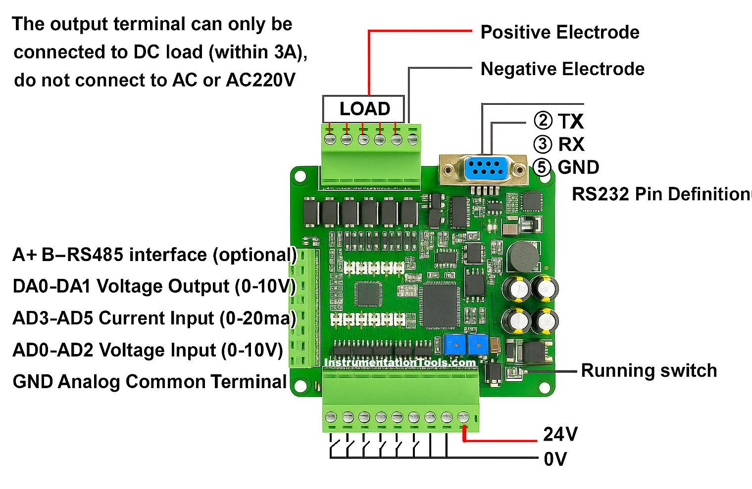
Pinout Wiring PLC FX3U Lollette
Pinout Wiring PLC FX3U Lollette.

The PLC cannot directly process raw analog voltage/current signals. Therefore, analog inputs must first pass through the PLC’s analog input module, which converts these signals into digital values using ADC (Analog-to-Digital Conversion) and other circuits.

The FX3U PLC features six analog input pins:

  • AD0 to AD2 for voltage signals (0-10V)
  • AD3 to AD5 for current signals (4-20mA)

In this program, we will utilize Analog Input AD1 for signal processing.

Testing Video

In this video, we tested the PLC hardware with a potentiometer as an analog input.

Testing Analog Input in Mitsubishi FX3U PLC Hardware

Analog Input Circuit with Potentiometer
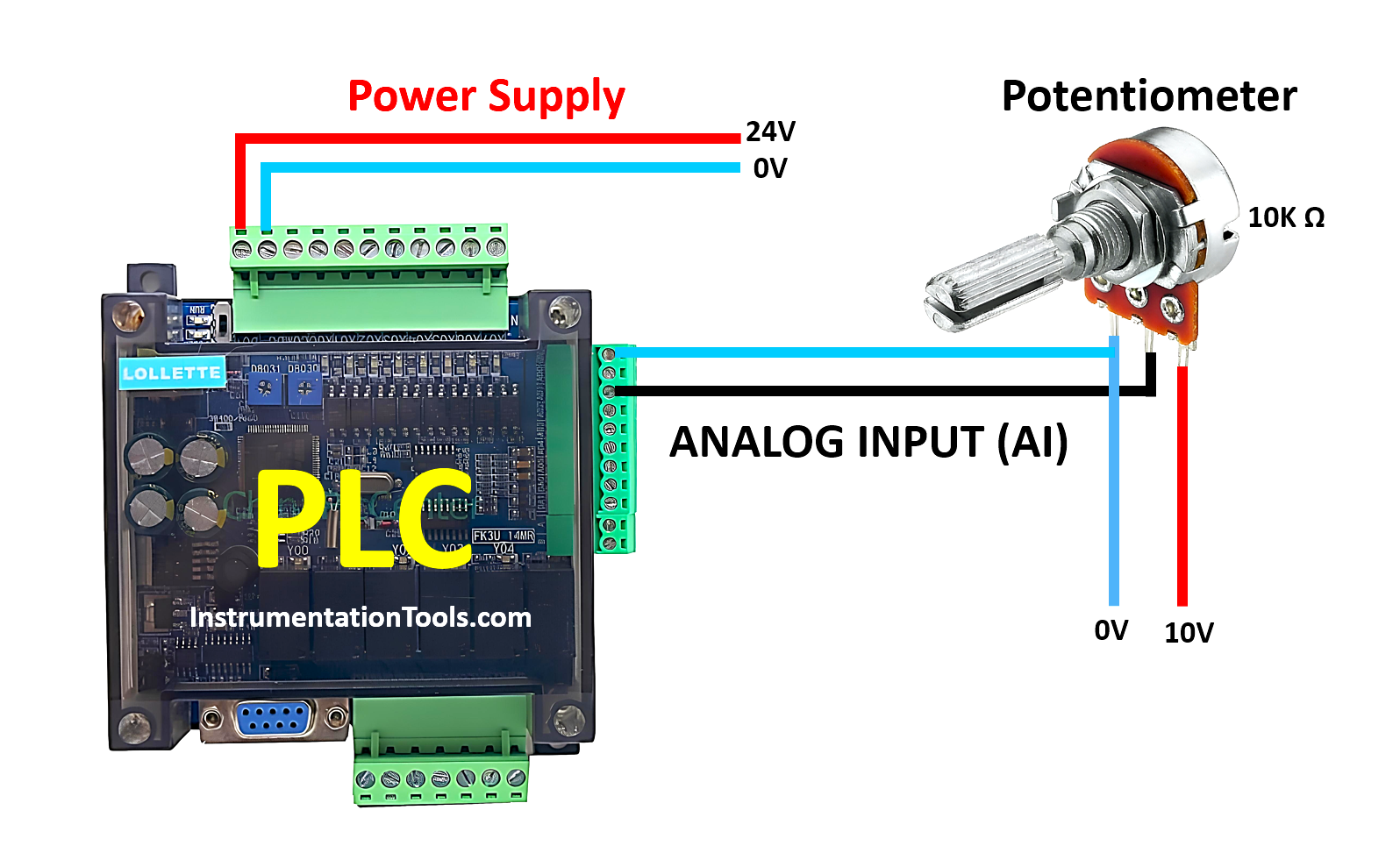
How to Use Analog Input in Mitsubishi FX3U LOLLETTE PLC

To adjust the voltage value, a 10kΩ potentiometer is required in our testing setup. The potentiometer will be connected to +10V and 0V (GND), while its output terminal will be linked to the Analog Input AD1 of the PLC. Additionally, the PLC requires a 24V DC power supply as its main power source.

Mitsubishi Analog Input Programming
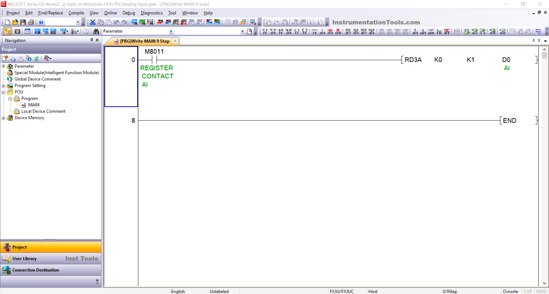
Mitsubishi Analog Input Programming

RUNG 0

In this rung, the normally open (NO) contact from REGISTER CONTACT AI (M8011) is a special register address used to activate the RD3A instruction.

The RD3A instruction is used to read the analog input data received.

The value “K0” refers to the module address being used, and “K1” specifies the analog input channel being accessed (AD1).

The memory word AI (D0) is used to store the analog input data received from AD1. The analog input data will be converted into a 12-bit value (ranging from 0 to 4095).

Read Next:

  • PLC Program for Sequential Motor Control
  • Program for Light Sequences using Timers
  • Structured Text Sequential Process Data Storage
  • Run 4 Motors Sequentially from 1 Push button
  • Mitsubishi PLC Training Course and Tutorials

Don't Miss Our Updates
Be the first to get exclusive content straight to your email.
We promise not to spam you. You can unsubscribe at any time.
Invalid email address
You've successfully subscribed !

Continue Reading

Types of Interlocks
Analog Measurement using Ladder Logic
Timer during Motor Direction Change PLC Program
Micro Memory Card (MMC) in Siemens PLC
How to Convert Voltage to Current using Resistor ?
Boolean Logic to PLC Programming
Share This Article
Facebook Whatsapp Whatsapp LinkedIn Copy Link
Share
Leave a Comment

Leave a Reply Cancel reply

Your email address will not be published. Required fields are marked *

Stay Connected

128.3kFollowersLike
69.1kFollowersFollow
210kSubscribersSubscribe
38kFollowersFollow

Categories

Explore More

History of Programmable Logic Controllers (PLC)
Various Types of Delta PLC used in Industrial Automation
PLC Structured Text Program for Output Generation via Equations
PLC Input Output Modules
Parking Lights PLC Program Explained with Video
How to Use ModScan Software for Testing Modbus Communication?
RSLogix 5000 PLC Programming Procedure
Attendance System PLC Program using CX-Programmer

Keep Learning

FIFO and LIFO Sequences in PLC

What are FIFO and LIFO Sequences in PLC?

Claw Machine PLC Programming

Doll Claw Machine using Omron PLC Programming

Automatic Car Door Simulation

Automatic Door Operation PLC Programming and Simulation

PLC Problems Troubleshooting

PLC Problems Troubleshooting

Programmable Logic Controller Practice Tests

Programmable Logic Controller Practice Tests

Start the Counting from a Preset Value in PLC

Start the Counting from a Preset Value in PLC

How to Link SQL With Indusoft Web Studio

How to Use an SQL Server with Indusoft Web Studio?

Networked SCADA Architecture

Types of SCADA System Architecture

Learn More

HART Communication Problems

HART Communication Problems

gas chromatograph principle

Online Gas Chromatograph Principle

Configure Analog Inputs and Outputs in Delta PLC

How to Configure Analog Inputs and Outputs in Delta PLC?

How to Test a Transistor

How to Test a Transistor ?

30% Feed Control Valve

Purpose of 100% and 30% Feed Control Valves in a Power Plant

PLC Examples for calling functions in SCL

How to Insert Block Calls in SCL Language?

Coriolis Flow Meter Inaccuracy

Coriolis Flow Meter Uncertainty and Inaccuracy

RF Admittance Level Transmitter Working Principle

RF Admittance Level Transmitter Working Principle

Menu

  • About
  • Privacy Policy
  • Copyright

Quick Links

  • Learn PLC
  • Helping Hand
  • Part Time Job

YouTube Subscribe

Follow US
All rights reserved. Reproduction in whole or in part without written permission is prohibited.
Welcome Back!

Sign in to your account

Username or Email Address
Password

Lost your password?