Instrumentation engineering root cause analysis of ammonia failed closed feed ball valve loading to ship tank.
| Article Type: | Root Cause Analysis (RCA) |
| Category: | Instrumentation |
| Equipment Type: | Instruments |
| Author: | S. Raghava Chari |
Note: This root cause analysis (RCA) is from real-time scenarios that happened in industries during the tenure of two or three decades ago. These articles will help you to improve your troubleshooting skills and knowledge.
Problem: Frantic 1 AM shore installation phone call jolted the author out of deep slumber below two comforter layers in his 6o C chill weather not heated room.
The instrument engineer Murthy’s timid voice said, “Sir, the ammonia feed ball valve to the ship tank has closed; ammonia ship loading stopped.
The frantic shift engineer thunders that each day or part delayed ship costs $ 25000 demurrage; hence restore the loading immediately. Neither I nor the project engineer Akbar know what to do. Please come and guide us sir.”
The author who had joined the plant just a week ago was also new to ship Loading Arms. Hence, he, the plant superintendent (PS) and the instrument engineer (IE) reached the LA control room within 25 minutes.
They found the yellow lamp labeled ‘ship in warning area; ball valve closed” glowing. The crew said they heard the alarm and silenced the hooter, found the NH3 inlet to the LA ball valve closed.
The author gathered that the hydraulic Cylinder operated 6”x300 # ball valve had closed. None could answer his query; under what conditions the LA relay logic (LRL) closes the ball valve.
Rather, the PS sarcastically said, “Ragha please stop your Phd research now; open the ball valve by hook or crook; let the loading resume and ship leave; then do all the research you want.”
The author told, “Sheriff (the PS’s name), some unsafe condition has alarmed and shut the ball valve (BV). We should find the cause and remove it; blindly opening the BV is dangerous.” The more annoyed PS said, “Ragha I assume responsibility; open the BV hook or crook and let the loading start.”
The author got the bypass valve across the hyd cyl opened. Even 4 persons with a 1.5 m long 2” pipe inserted in the BV arm could not budge the valve. It required so much torque!
The author got the LRL cover removed. Fortunately, it had a clear drawing showing the terminal numbers sending 24 V actuating signals. He detached the 24 V DC wire feeding close command to the BV and touched the BV open terminal for a minute.
The BV opened as if magic and loading resumed. All were jubilant and Sheriff triumphantly told, “Ragha didn’t I tell you not to worry and open the BV; that did it and now loading is progressing.
The author told diffidently, “Sheriff, I don’t know what danger we got into; at least call an extra supervisor to watch the loading; put him and all on alert; he should instantly trip the liquid ammonia (LA) feed pump, close its discharge as fast as possible and detach the LA from the ship, no matter ship not loaded fully.” They waited till the extra supervisor arrived and understood the instructions.
The remining 25% loading took 4‑hours and the ship departed event free.
But the elation was short lived! The author studied the system in detail the very next morning and thanked God for averting a disaster that could have happened! LA system study taught the following:
The LA is a vertical Pipe column with ball jointed top swiveling arm capable of 60o CW horizontal travel and 60o CCW travel. Few more ball jointed tubular arms capable of 60o either direction horizontal travel and vertical travels complete the LA.
A liquid NH3 pump draws from port storage tank. Its discharge pipe feeds the NH3 to the LA column via a ball valve. The final LA member is a 6” 150 # RF flange ended short pipe and hydraulic cyl operated clamp for clamping on to the shops tank flange.
The Relay Logic Circuit located close to the LA control the members travels, ball valve closing/opening and clamping and de-clamping the LA to the ship flange.
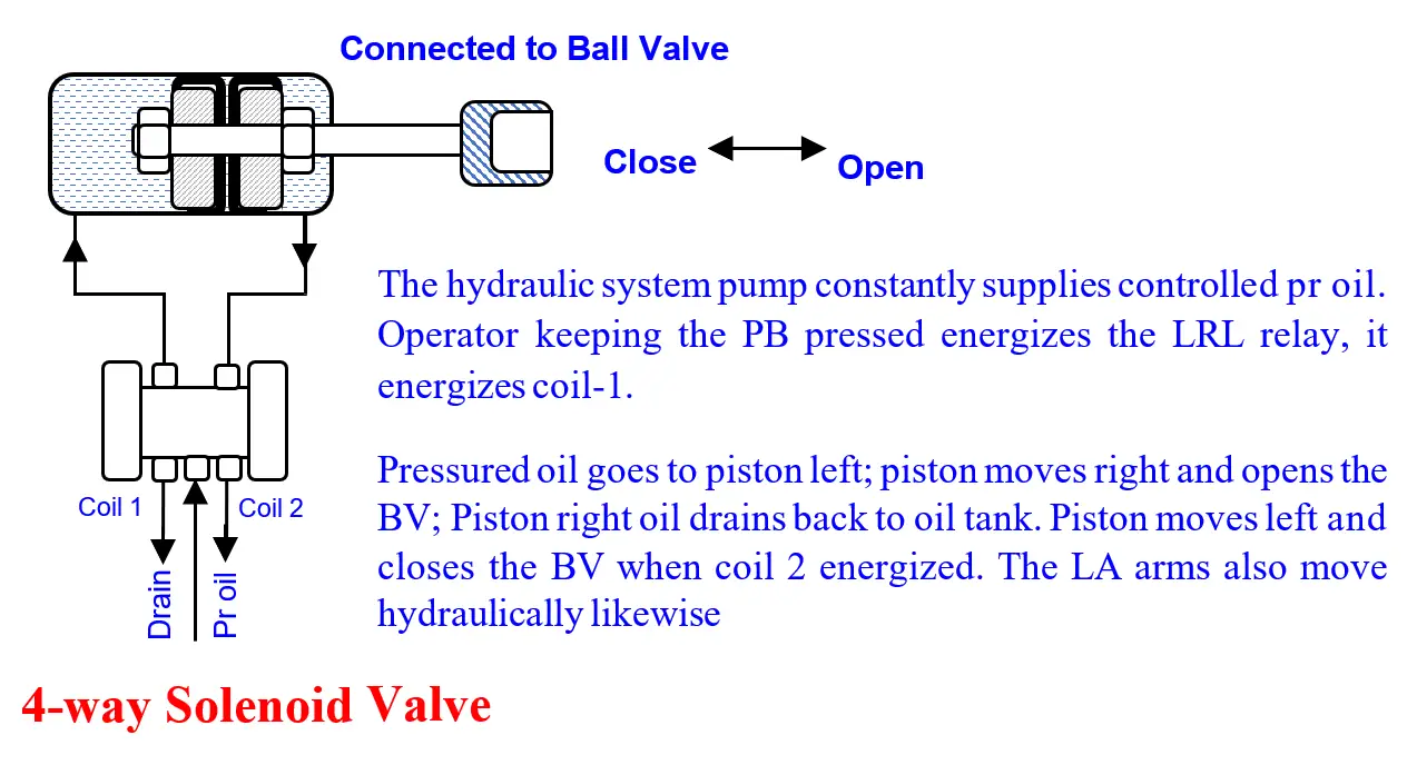
Hydraulic cylinders (HC) receive oil via the relays controlled 4-way solenoids for the various LA actions. Push Buttons activate the relays. Fig 1 shows how the LRL swivels the LA arm and Fig 2, BV open. The other actuations are identical.
In addition, the LA activating relay logic protects the LA thus:
From the above learning the author guessed as follows:
Having experienced a near miss incident, the author took the following steps to avert recurrence.
Thanks to these precautions, the plant enjoys trouble and incidents free LA service then on.
Author: S. Raghava Chari
Do you face any similar issues? Share with us through the below comments section.
If you liked this article, then please subscribe to our YouTube Channel for Instrumentation, Electrical, PLC, and SCADA video tutorials.
You can also follow us on Facebook and Twitter to receive daily updates.
Read Next:
PLC ladder logic design to control 3 motors with toggle switch and explain the program…
VFD simulator download: Master the online tool from the Yaskawa V1000 & programming software for…
The conveyor sorting machine is widely used in the packing industries using the PLC program…
Learn the example of flip-flop PLC program for lamps application using the ladder logic to…
In this article, you will learn the STAR DELTA programming using PLC controller to start…
Lube oil consoles of rotary equipment packages in industrial process plants are usually equipped with…

