shield is a metallic covering enclosing an insulated conductor or group of conductors. Though sometimes similar in appearance, shields for electronic and power cables perform very different functions. Electronic cable shields serve to both minimize the effect of external electromagnetic signals on the conductors in the cable and to reduce the radiated signal from the cable to an acceptable level. Power cable shields, on the other hand, help protect the user from shock hazards and increase cable reliability by preventing partial discharges (corona) in cables.
Power Cable
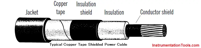
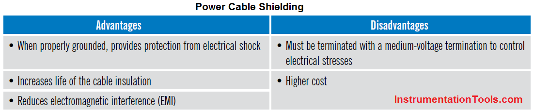
The use of shields in power cables reduces electrical shock hazard to people and provides uniform distribution of electrical stresses throughout the insulation. A uniform distribution of electrical stress extends the life of the cable by eliminating partial discharges. The NEC requires most cable rated 2,400 V or greater to be shielded. The various components of a power cable shield are discussed below.
1.Conductor Shield (Strand Shield)
The nonround geometry of stranded conductors permits air gaps between the outer surface of the conductor and the inner surface of the insulation. Without a stress control layer, high electric fields cause partial discharges within these gaps, which can harm the insulation. Energetic ions bombard the insulation, break molecular bonds and degrade the insulation. Microscopic channels called “trees” may form and ultimately cause premature failure of the insulation. Thus, the primary purpose of the conductor shield is to provide a smooth, continuous and void-free interface between the conductor and insulation.
There are two basic types of conductor shields – “conductive” and “emission” shields. An emission shield uses a material with a high dielectric constant to do its job. The most popular type, however, is the conductive shield. It is a material (either an extruded carbon black loaded polymer or carbon black impregnated fabric tape) with electrical conductivity midway between that of a metallic conductor such as copper and that of an insulation such as XLP. Such a material is commonly referred to as a “semiconductive” shield (not to be confused with semiconductors, i.e., transistors, used in the electronics industry).
Semiconductive shields must be as smooth, cylindrical and clean as possible to avoid electrical stress concentrations that can lead to insulation damage.
2.Outer Shield (Insulation Shield)
The insulation shield plays much the same role as the conductor shield in protecting the insulation from the damaging effects of corona, but at the outside of the cable’s insulation. It too must remain in intimate contact with the insulation and be free of voids and defects. The insulation shield material is either electrically conductive or made of a high dielectric constant material and provides a uniform electrical field within the insulation. The insulation shield also provides an important safety function at terminations and splices where the metallic part of the shield may not completely cover the cable insulation surface. Volume resistivity of the insulation shield is normally less than 500 ohm-meters.
3.Copper Tape Shields
The copper tape used in power cable shields is usually 5 mils thick and 1 to 1 1/2 inches wide. It is generally helically applied over a semiconducting polymer insulation shield. Power cables rated 5 to 35 kV and up frequently utilize copper tape as the metallic component of the metal/polymer shielding system. In combination with the extruded insulation shield, a copper tape shield increases insulation life by maintaining uniform electrical stress throughout the cable insulation and provides low end-to-end resistance of the shield system.
4.Wire Shields
Metallic wire shields on power cables come in two basic types: helically applied copper wires and UniShield.
Helically applied copper wire shields are sometimes used on 5 through 35 kV and higher rated power cables. They are sometimes used in combination with copper tape to provide additional shield fault current capacity.
UniShield cables have six corrugated copper wires longitudinally imbedded in a conducting CPE jacket. The wires can be used as “ripcords” to reduce termination time during installation.
Electronic Cable
Electronic cable shielding provides an efficient way to manage electromagnetic interference (EMI).
When a shielded cable is present in an ambient electromagnetic field, an interference current is induced in the shield. The incident energy is partially reflected from the shield and partially absorbed by the shield and a small amount penetrates through the shield into the cable. The small amount of energy that makes it all the way through the shield generates an interference voltage in the signal carrying conductors of the cable. The smaller the interference voltage, the better the shield.
In addition to shielding effectiveness, electronic cable shields must satisfy a long list of electrical, mechanical, chemical and cost requirements. As a result, a diversified line of shield designs has evolved in the wire and cable industry.
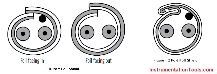
1.Foil Shield
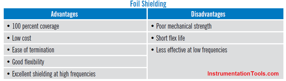
Foil shields are usually constructed of aluminum foil with a 1/2-mil thick polyester backing. This backing provides mechanical strength. The shield can be overlapped (Below Fig) with the foil facing in or the foil facing out. This overlap creates a slot where signal leakage through the shield can occur. The “Z” fold (Below Fig) construction provides the best electrical isolation between shields of adjacent pairs as well as 100 percent coverage. A tinned copper drain wire is placed in contact with the foil side of the shield to provide easier grounding of the shield at the cable terminations.
Foil shields are most common in electronic and coaxial cables. Foil shields provide excellent protection from electromagnetic interference, especially
at high frequencies.
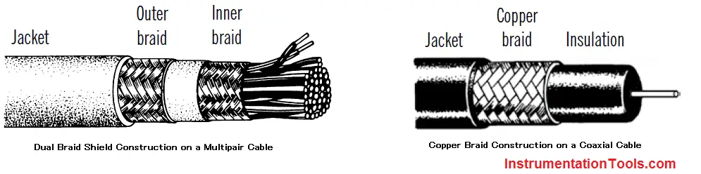
2.Copper Braid Shield
braid shield typically consists of copper wire ranging in size from 32 to 40 AWG braided into a mesh around the cable core. The tightness of the braid determines the percent coverage. Typical coverage ranges from 60 percent to 90 percent. Generally, the higher the coverage the better the shield.
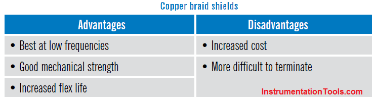
Braid shields are typically used on coaxial cables and on low-speed communication cables. Braid shields are most effective at low frequencies. Braid shields are also commonly used on cables where increased flex life and mechanical strength are required.
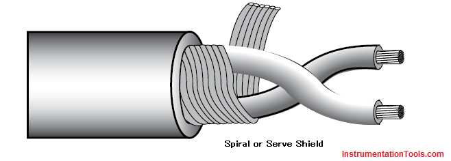
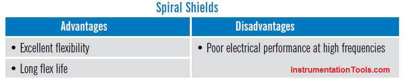
3.Spiral (Serve) Shield
Spiral or serve shields, as they are sometimes called, are typically constructed with bare or tinned copper wires from 32 to 40 AWG in size that are helically applied in a flat or ribbon configuration (Below Fig). Spiral shields range in coverage from 80 percent to about 97 percent.
Spiral shields are used primarily in audio, microphone and retractile cord cables where extreme flexibility and a long flex life are required. Spiral shields perform best when used at low (audio) frequencies.