SIL-3 introduces a significantly higher level of safety integrity and demands a more rigorous approach to system design and PLC programming. Before beginning any SIL-3 implementation, it is critical to be fully familiar with the requirements and behavior expected at the SIL-2 level.
SIL-3 is not a separate or independent concept; it builds on existing safety mechanisms by increasing redundancy, strengthening diagnostics, and tightening fault-handling rules. If concepts such as multi-channel voting, fault detection, safe-state enforcement, and controlled reset logic are not clearly understood at SIL-2, then developing reliable SIL-3 logic becomes impractical.
For this reason, a solid understanding of SIL-2 principles is a prerequisite. Readers are encouraged to review the earlier SIL-2 discussion before proceeding. In this section, we will examine how SIL-3 safety logic is structured and implemented in PLC programming.
SIL-3 Safety PLC
Continuing the same principles of SIL-2, SIL-3 introduces one of the most stringent levels of functional safety and requires a disciplined approach long before any PLC logic is written. At this level, safety implementation is driven by system architecture, fault tolerance, and diagnostic effectiveness rather than by programming techniques alone.
SIL-3 applications demand multiple layers of redundancy, continuous fault monitoring, and deterministic transition to a safe state under any single failure or combination of failures. Attempting to develop SIL-3 logic without first understanding these expectations leads to unsafe and non-compliant designs.
For this reason, a clear understanding of the governing principles of SIL-3 is essential before beginning PLC programming.
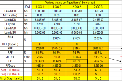
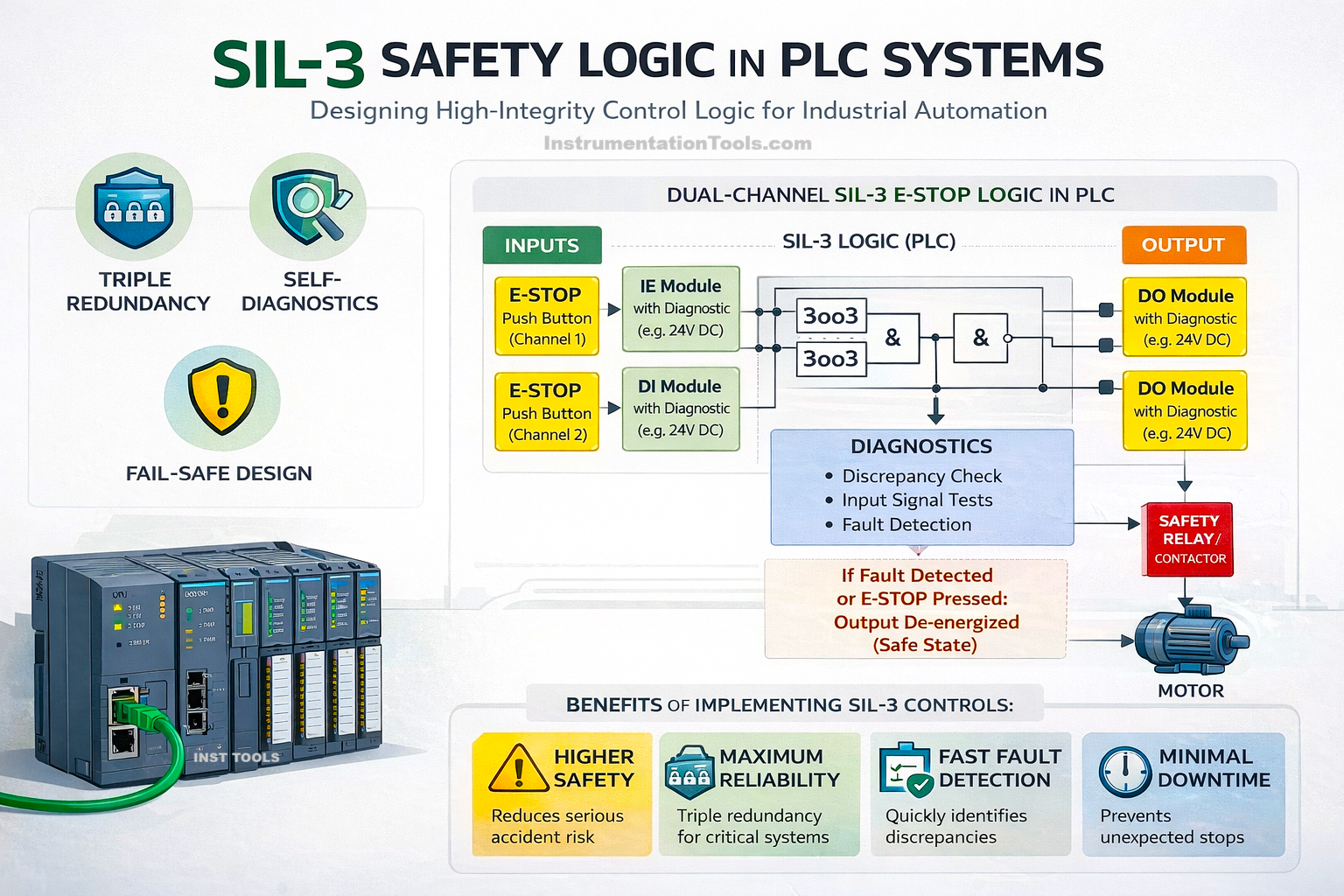
- In SIL-3 applications, the minimum voting architecture is typically 2oo3, ensuring that at least two independent sources confirm a hazardous condition before a safety action is triggered. This requirement improves decision reliability and reduces the risk of spurious trips or dangerous failures compared to simpler architectures sometimes used in SIL-2.
- SIL-3 relies more heavily on multiple independent sensors measuring the same process variable. The system must be able to validate process conditions using agreement between sources, rather than trusting a single measurement path, as may be acceptable in some SIL-2 designs.
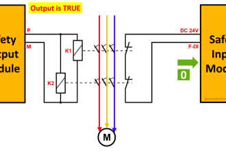
- While output feedback monitoring is recommended and often implemented in SIL-2 systems, it is almost always mandatory in SIL-3. The safety function must verify that the final element (valve, contactor, relay) has actually moved to the safe state, not just that a command was issued.
- SIL-2 allows some flexibility in output design and monitoring based on risk assessment. In SIL-3, such flexibility is significantly reduced, and the output path is treated as a critical part of the safety function with strict monitoring and fault detection requirements.
- SIL-2 systems may allow limited operation with mismatch alarms under controlled conditions, depending on the Safety Requirement Specification. In SIL-3, a persistent mismatch between redundant channels is generally considered unacceptable and typically results in a transition to the safe state.
- Operation with reduced redundancy may be temporarily permitted in SIL-2 under defined conditions. In SIL-3 systems, degraded operation is either heavily restricted or not permitted at all, as it directly impacts the achievable risk reduction.
- SIL-3 requires significantly higher diagnostic coverage than SIL-2. Faults such as sensor drift, frozen values, loss of redundancy effectiveness, and hidden failures must be detected more reliably and within shorter timeframes.
- In SIL-3, the response to detected faults is more aggressive. Many diagnostic faults that might generate alarms or warnings in SIL-2 will directly force a safe shutdown in SIL-3 to maintain the required safety integrity.
- For SIL-3, the logic structure, diagnostics, voting method, and fault responses are strictly defined in the Safety Requirement Specification. Any deviation from the SRS is not permitted, even if the PLC logic appears to function correctly.
- SIL-2 allows limited engineering judgment in selecting architectures and responses, provided safety targets are met. SIL-3 significantly reduces this freedom; the design is largely dictated by safety analysis and certification requirements rather than programming preference.
Writing SIL-3 Safety Logic in PLC Systems
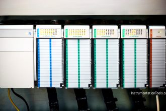
- PLC must be SIL-3 certified. So accordingly, the dedicated CPU, fail-safe IO modules, and TUV-approved firmware must be selected to configure the required safety logic.
- SIL-3 does not require new PLC instructions or algorithms beyond those already used in SIL-2. The same basic logic patterns are used, but with stricter constraints. Every possible condition—including invalid data, diagnostic uncertainty, or unexpected task behavior—must result in a clearly defined outcome. Any undefined or ambiguous state is considered unsafe.
- In SIL-3, conditions that might be ignored or logged in SIL-2 must be explicitly handled in the logic, typically by forcing the system to a safe state. The program must not assume correct sensor behavior, task execution, timing, or data validity. All such assumptions must be checked and verified in logic or by certified system diagnostics.
- SIL-3 logic must execute predictably every scan. Implicit state changes, hidden dependencies, or compiler-dependent behavior are not acceptable.
- Safety code must be completely isolated from standard control logic. Shared variables, shared timers, or mixed execution paths are not allowed.
- All inputs, intermediate values, and states must be validated. Value correction, auto-clamping, or silent recovery techniques are avoided in favor of fault detection.
- Design choices that improve availability or operator convenience in SIL-2 are generally removed or heavily restricted in SIL-3.
- The programmer’s role in SIL-3 is not to optimize logic, but to strictly implement what is defined in the Safety Requirement Specification—without deviation.
SIL-3 programming does not add complexity to the code; it removes freedom from the programmer that was available in SIL-2. In this way, we saw how to write SIL-3 logic in PLC programming.