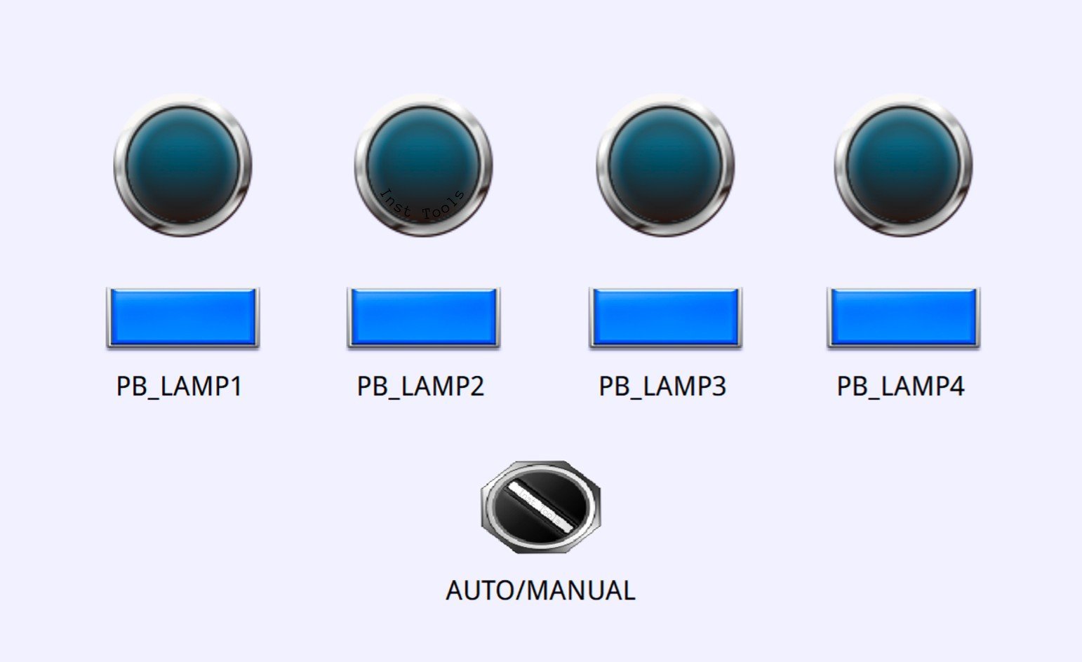
This article will explain PLC exercise for a Lamp logic that can be operated automatically or manually using Siemens PLC programming. This PLC system will set 4 Lamp outputs to turn ON in a certain order at different time intervals, and allows manual control of each Lamp via a button.
Program Objective
System Sequence:
A. Automatic Mode (Auto):
- Change the selector switch position to “Auto” to activate the system in automatic mode.
- When the system is running in this mode:
- Lamp-1 lights up for 5 seconds.
- Lamp-1 turns Off, then Lamp-2 turns On for 5 seconds.
- Lamp-2 turns Off, then Lamp-3 turns On for 6 seconds.
- Lamp-3 goes Off, followed by Lamp-4 On for 4 seconds.
- Once all steps are completed, the system will repeat the sequence at the same interval.
B. Manual Mode:
- Change the selector switch position to “Manual” to operate the light manually.
- The light can only be turned on using the following buttons:
- Button-1 for Lamp-1.
- Button-2 for Lamp-2.
- Button-3 for Lamp-3.
- Button-4 for Lamp-4.
Mapping Details
| S.No. | Comment | Input (I) | Output (Q) | Memory Word | Memory Bit | Timer |
|---|---|---|---|---|---|---|
| 1 | START | I0.0 | ||||
| 2 | STOP | I0.1 | ||||
| 3 | SELECTOR_SWITCH | I0.2 | ||||
| 4 | PB_LAMP1 | I0.3 | ||||
| 5 | PB_LAMP2 | I0.4 | ||||
| 6 | PB_LAMP3 | I0.5 | ||||
| 7 | PB_LAMP4 | I0.6 | ||||
| 8 | LAMP1 | Q0.0 | ||||
| 9 | LAMP2 | Q0.1 | ||||
| 10 | LAMP3 | Q0.2 | ||||
| 11 | LAMP4 | Q0.3 | ||||
| 12 | TIMER1 | DB1 | ||||
| 13 | TIMER2 | DB2 | ||||
| 14 | TIMER3 | DB3 | ||||
| 15 | TIMER4 | DB4 | ||||
| 16 | SYSTEM_ON | M0.0 | ||||
| 17 | IR_LAMP1 | M0.1 | ||||
| 18 | IR_LAMP2 | M0.2 | ||||
| 19 | IR_LAMP3 | M0.3 | ||||
| 20 | IR_LAMP4 | M0.4 | ||||
| 21 | IR_TIMER1 | M0.5 | ||||
| 22 | IR_TIMER2 | M0.6 | ||||
| 23 | IR_TIMER3 | M0.7 | ||||
| 24 | IR_TIMER4 | M1.0 |
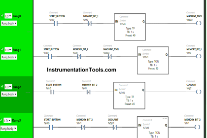
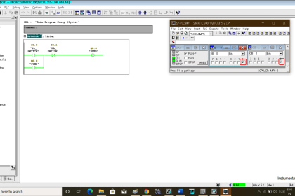
Siemens PLC Lamp Logic
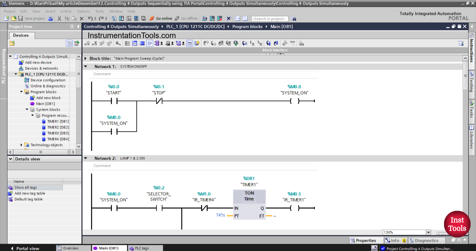
NETWORK 1 (SYSTEM ON/OFF)
In this network, when the START (I0.0) button is pressed, the memory bit SYSTEM_ON (M0.0) will be in the HIGH state. Even though the START (I0.0) button has been released, the memory bit SYSTEM_ON (M0.0) will remain in the HIGH state. Because it uses Latching.
If the STOP (I0.1) button is pressed, the memory bit SYSTEM_ON (M0.0) will be in the LOW state.
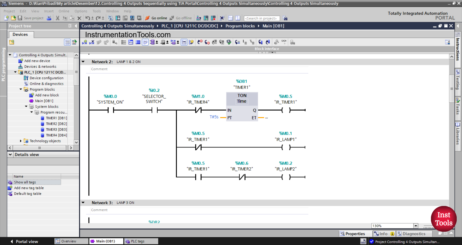
NETWORK 2 (LAMP 1 & 2 ON)
In this Network, the timer TIMER1 (DB1) will start counting, and the memory bit IR_LAMP1 (M0.1) will be in the HIGH state when the NO contact of the memory bit SYSTEM_ON (M0.0) and the NO contact of the selector switch SELECTOR_SWITCH (I0.2) are in the HIGH state.
The TIMER1 (DB1) timer will count up to 5 seconds, and when the TIMER1 (DB1) timer has finished counting, the memory bit IR_LAMP1 (M0.1) will be in LOW state, the memory bits IR_TIMER1 (M0.5) and IR_LAMP2 (M0.2) will be in the HIGH state.
When the NC contact of the IR_TIMER4 (M1.0) timer is in the HIGH state, the TIMER1 (DB1) timer will be reset.
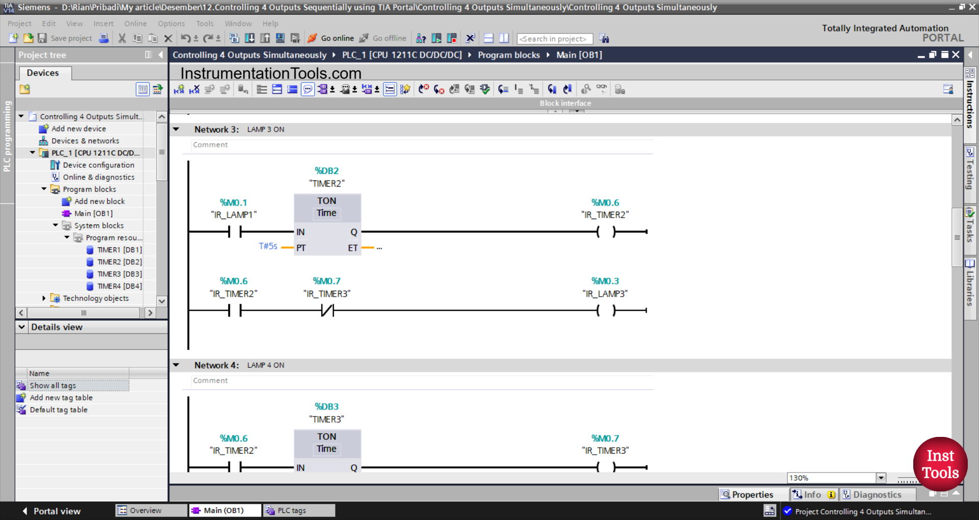
NETWORK 3 (LAMP 3 ON)
In this network, the memory bit IR_LAMP2 (M0.2) in the HIGH state and the timer TIMER2 (DB2) will start counting when the NO contact of the memory bit IR_LAMP1 (M0.1) is in the HIGH state.
The TIMER2 (DB2) timer will count up to 5 seconds, and after it has finished counting, the memory bits IR_LAMP3 (M0.3) and IR_TIMER2 (M0.6) will be in the HIGH state.
The memory bit IR_LAMP3 (M0.3) will be in the LOW state when the NC contact of the memory bit IR_TIMER3 (M0.7) is in the HIGH state.
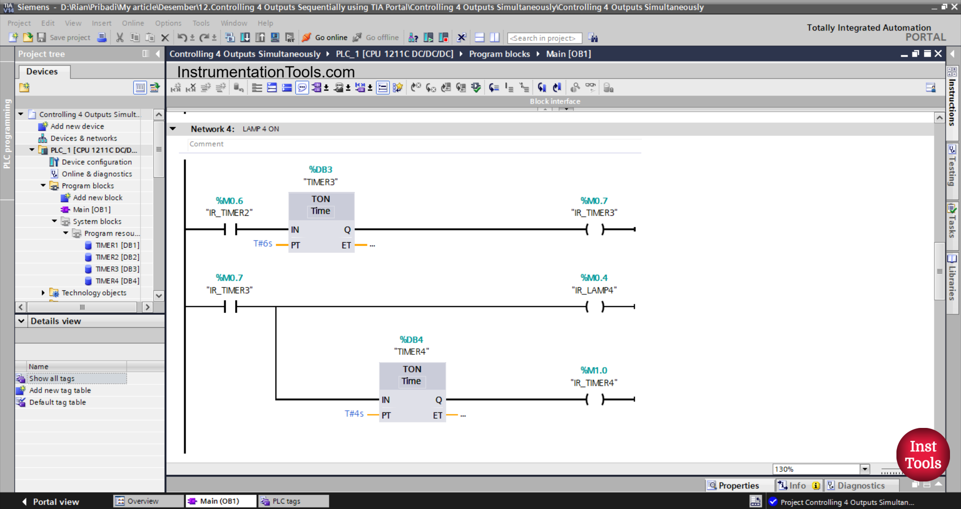
NETWORK 4 (LAMP 4 ON)
In this Network, the TIMER3 (DB3) timer will start counting if the NO contact of the memory bit IR_TIMER2 (M0.6) is in the HIGH state.
The TIMER3 (DB3) timer will count up to 6 seconds, and after it has finished counting, the memory bits IR_TIMER3 (M0.7) and IR_LAMP4 (M0.4) will be in the HIGH state.
Next, the TIMER4 (DB4) timer will start counting up to 4 seconds, and after it has finished counting, the memory bit IR_TIMER3 (M1.0) will be in the HIGH state.

NETWORK 5 (OUTPUT LAMP 1)
In this Network, the output LAMP_1 (Q0.0) will be ON if the NO contact of the memory bit SYSTEM_ON (M0.0) is in the HIGH state, the NC contact of the selector switch SELECTOR_SWITCH (I0.2) is in the LOW state, and the PB_LAMP1 (I0.3) button has been pressed.
Or, the output LAMP_1 (Q0.0) will be ON if the NO contact of the memory bit IR_LAMP1 (M0.1) is in the HIGH state.
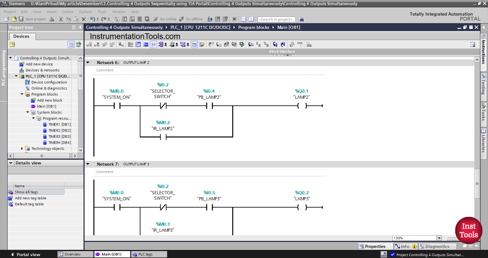
NETWORK 6 (OUTPUT LAMP 2)
In this network, the LAMP2 (Q0.1) output will be ON if the NO contact of the memory bit SYSTEM_ON (M0.0) is in the HIGH state, the NC contact of the selector switch SELECTOR_SWITCH (I0.2) is in the LOW state, and the PB_LAMP2 (I0.4) button has been pressed.
Or, the output of LAMP2 (Q0.1) will be ON if the NO contact of the memory bit IR_LAMP2 (M0.2) is in the HIGH state.

NETWORK 7 (OUTPUT LAMP 3)
In this network, the LAMP3 (Q0.2) output will be ON if the NO contact of the memory bit SYSTEM_ON (M0.0) is in the HIGH state, the NC contact of the selector switch SELECTOR_SWITCH (I0.2) is in the LOW state, and the PB_LAMP3 (I0.5) button has been pressed.
Or, the LAMP3 (Q0.2) output will be ON if the NO contact of the memory bit IR_LAMP3 (M0.3) is in the HIGH state.
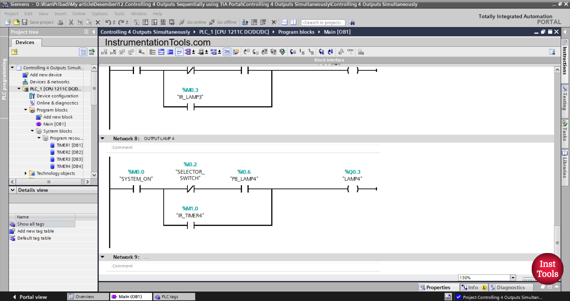
NETWORK 8 (OUTPUT LAMP 4)
In this Network, the LAMP4 (Q0.3) output will be ON if the NO contact of the memory bit SYSTEM_ON (M0.0) is in the HIGH state, the NC contact of the selector switch SELECTOR_SWITCH (I0.2) is in the LOW state, and the PB_LAMP4 (I0.6) button has been Pressed.
Alternatively, the LAMP4 (Q0.3) output will be ON if the NO contact of the memory bit IR_LAMP4 (M0.4) is in the HIGH state.
Read Next:
- Siemens PLC TIA Portal: Cargo Elevator for 3 Floors
- TIA Portal: Automatic Door Opener Programming
- Basic Arithmetic Programming in Mitsubishi PLC
- Siemens PLC Programming Exercise with Delay Timers
- PLC Project Download: Fruit Sorting by Weight and Color