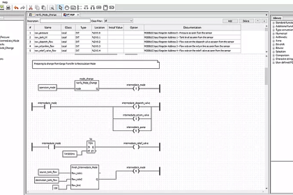
This article discusses a multi-level parking control program using the Siemens TIA Portal. The PLC system is used to efficiently manage the vehicle parking process by providing real-time information on parking slot availability on each floor. Through indicator lights, drivers can easily identify which floor still has empty slots, making it easier to choose a parking location. The PLC system records every car entering and exiting to monitor the number of available slots. When the parking area is full, the system will automatically issue a warning and prevent additional vehicles from entering.
Program Objective
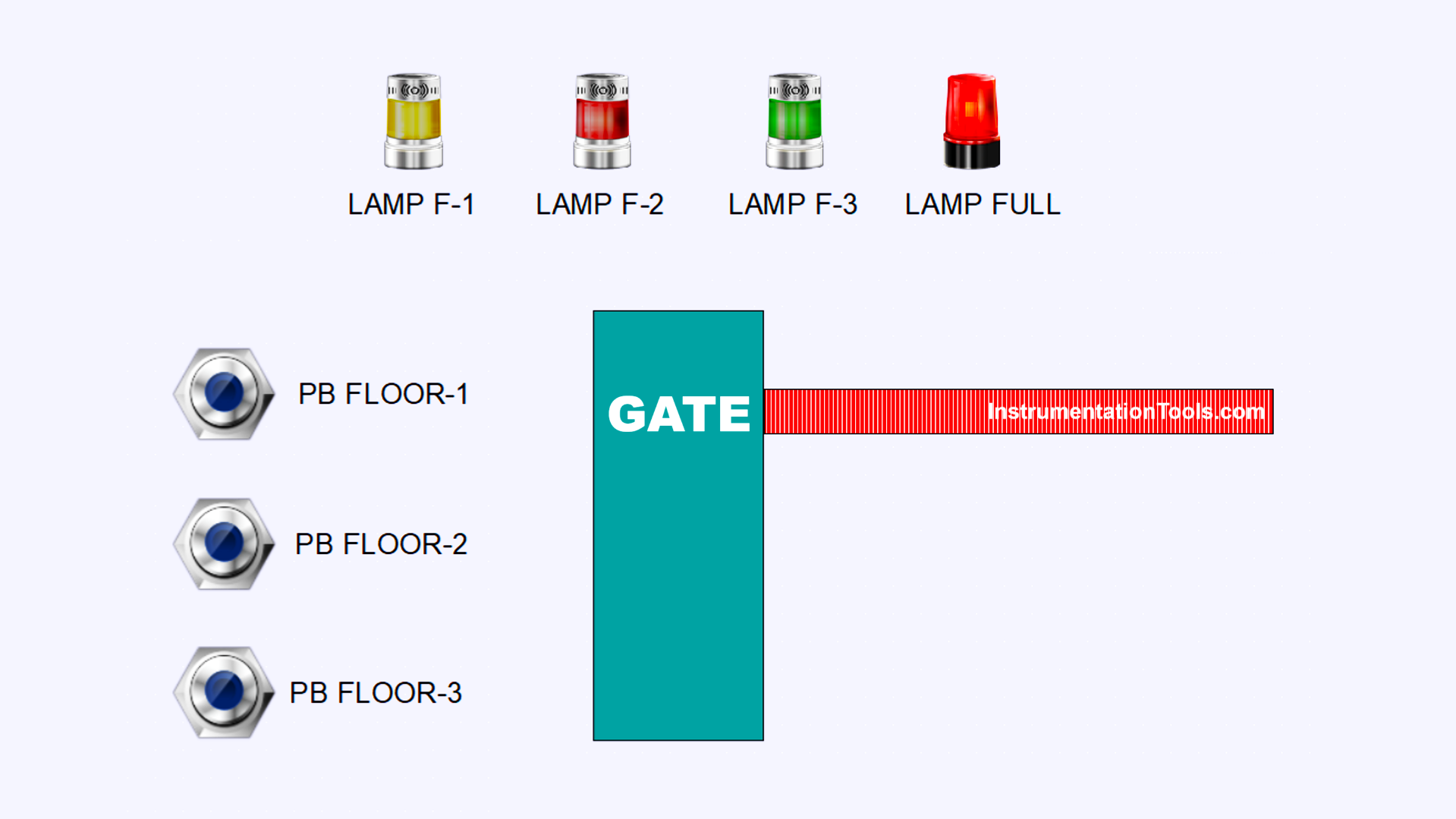
Parking Process in the Automatic Parking System
- Vehicle Detection
A sensor detects an incoming vehicle. The system immediately checks for available parking slots on each floor. - Parking Slot Monitoring
Each floor contains 10 parking slots and an individual exit gate. An exit sensor is installed on each floor to detect vehicles leaving the area. - Automatic Slot Update
When the exit sensor is triggered, the system automatically decreases the count of parked vehicles on that floor. - Parking Floor Selection
If multiple floors have available slots, the driver selects the desired floor. The system logs the selected floor and increments the vehicle count accordingly. - Gate Access Control
After the floor selection, the entry gate opens automatically for 10 seconds to allow the vehicle to enter. - Full Parking Indicator
If all parking slots are occupied, the system activates the “FULL” indicator to inform that no space is available.
IO Mapping in TIA Portal
| S.No. | Comment | Input (I) | Output (Q) | Memory Bit | Memory Word | Timer |
|---|---|---|---|---|---|---|
| 1 | START | I0.0 | ||||
| 2 | STOP | I0.1 | ||||
| 3 | SENS_CAR | I0.2 | ||||
| 4 | PB_FLOOR1 | I0.3 | ||||
| 5 | PB_FLOOR2 | I0.4 | ||||
| 6 | PB_FLOOR3 | I0.5 | ||||
| 7 | SENS_OUT1 | I0.6 | ||||
| 8 | SENS_OUT2 | I0.7 | ||||
| 9 | SENS_OUT3 | I1.0 | ||||
| 10 | LAMP_FLOOR1 | Q0.0 | ||||
| 11 | LAMP_FLOOR2 | Q0.1 | ||||
| 12 | LAMP_FLOOR3 | Q0.2 | ||||
| 13 | GATE_OPEN | Q0.3 | ||||
| 14 | LAMP_FULL | Q0.4 | ||||
| 15 | COUNT_FLOOR1 | MW2 | ||||
| 16 | COUNT_FLOOR2 | MW4 | ||||
| 17 | COUNT_FLOOR3 | MW6 | ||||
| 18 | TIMER_GATE | DB1 | ||||
| 19 | SYSTEM_ON | M0.0 | ||||
| 20 | IR_TIMER_GATE | M0.1 | ||||
| 21 | CAR_DETECT | M0.2 | ||||
| 22 | IR_PB_FLOOR1 | M0.3 | ||||
| 23 | IR_PB_FLOOR2 | M0.4 | ||||
| 24 | IR_PB_FLOOR3 | M0.5 | ||||
| 25 | IR_SENS_OUT1 | M0.6 | ||||
| 26 | IR_SENS_OUT2 | M0.7 | ||||
| 27 | IR_SENS_OUT3 | M1.0 |
Multi-Level Parking Control Program
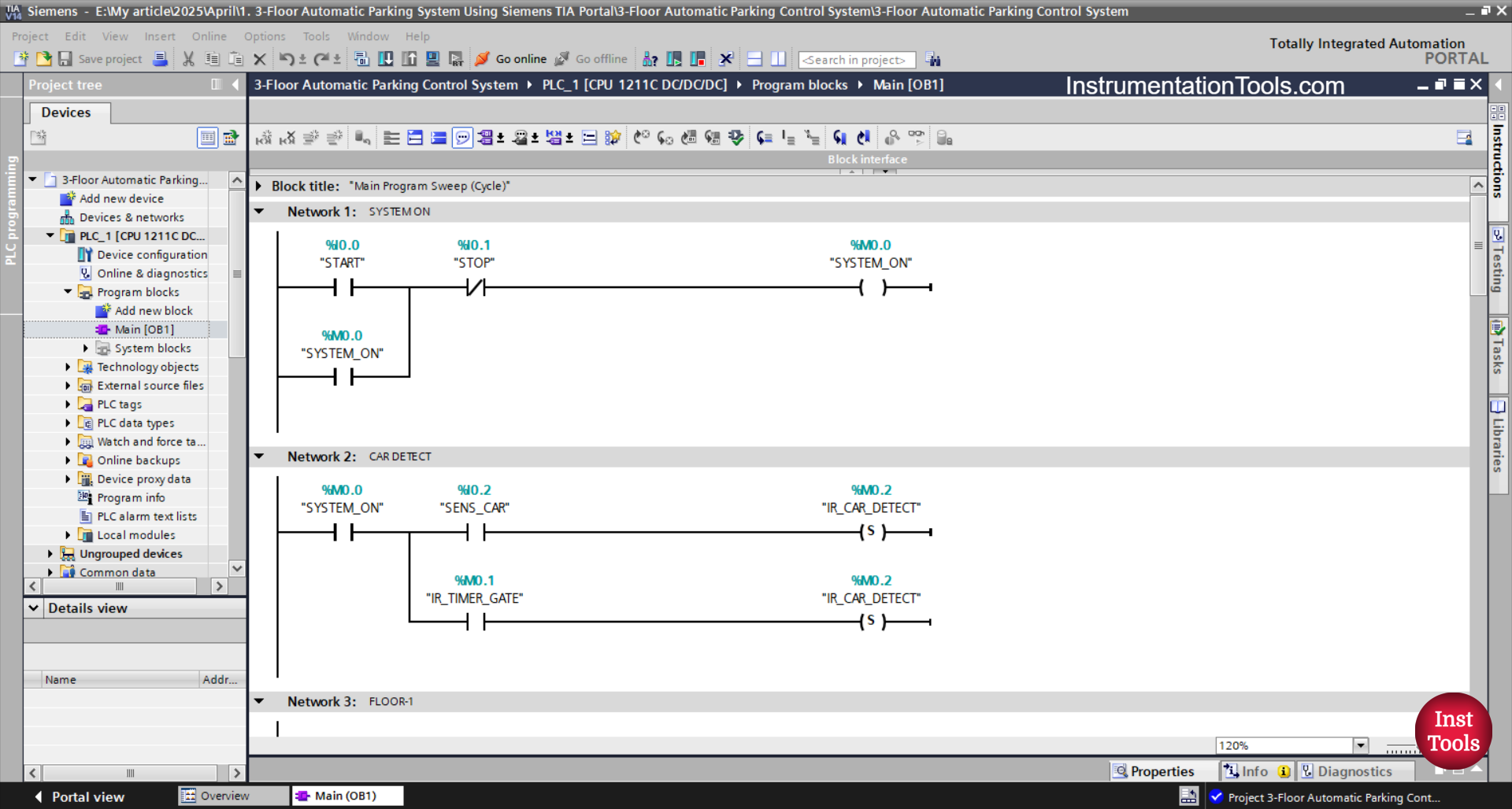
RUNG 1 (SYSTEM ON)
In this Rung, the memory bit SYSTEM_ON (M0.0) will be in a HIGH state if the START (I0.0) button is pressed. The memory bit SYSTEM_ON (M0.0) will remain in a HIGH state even though the PB_START (I0.0) button has been released. Because it uses Latching.
If the STOP (I0.1) button is pressed, then the memory bit SYSTEM_ON (M0.0) will return to a LOW state.
RUNG 2 (CAR DETECT)
In this Rung, the memory bit CAR_DETECT (M0.2) will be in a HIGH state when the NO contact of the memory bit SYSTEM_ON (M0.0) and the SENS_CAR (I0.2) sensor are in a HIGH state.
The memory bit CAR_DETECT (M0.2) will remain in the HIGH state even though the NO contact of the SENS_CAR (I0.2) sensor has been in the LOW state. Because it uses the SET Output instruction.
Because it uses the RESET Output instruction, the memory bit CAR_DETECT (M0.2) will be in the LOW state if the NO contact of the IR_TIMER_GATE (M0.1) timer has been in the HIGH state.

RUNG 3 (FLOOR-1)
In this Rung, the LAMP_FLOOR1 (I1.0) output will be ON if the NO contact of the memory bit CAR_DETECT (M0.2) and the memory word COUNT_FLOOR1 (MW2) is Less Than “15”.
Because the memory word COUNT_FLOOR1 (MW2) uses an Increment instruction, the value of the memory word COUNT_FLOOR1 (MW2) will increase (+1) if the PB_FLOOR1 (I0.3) button is pressed.
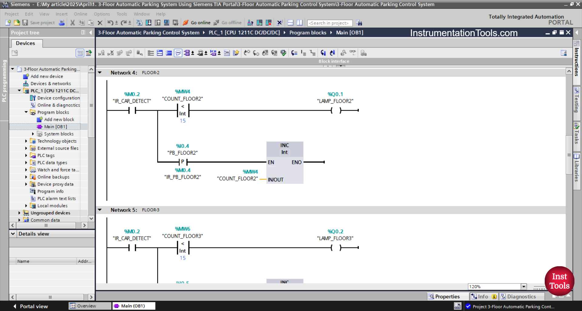
RUNG 4 (FLOOR-2)
In this Rung, the LAMP_FLOOR2 (Q0.1) output will be ON when the NO contact of the memory bit CAR_DETECT (M0.2) and the memory word COUNT_FLOOR2 (MW4) is Less Than “15”.
Because memory word COUNT_FLOOR2 (MW4) uses an Increment instruction, the value of the memory word COUNT_FLOOR2 (MW4) will increase by (+1) when the PB_FLOOR2 (I0.4) button is pressed.

RUNG 5 (FLOOR-3)
In this Rung, the LAMP_FLOOR3(Q0.2) output will be ON when the NO contact of the memory bit CAR_DETECT (M0.2) and the memory word COUNT_FLOOR3 (MW6) is Less Than “15”.
Because the memory word COUNT_FLOOR3 (MW6) uses an Increment instruction, the value of the memory word COUNT_FLOOR3 (MW6) will increase by (+1) when the PB_FLOOR3 (I0.5) button is pressed.
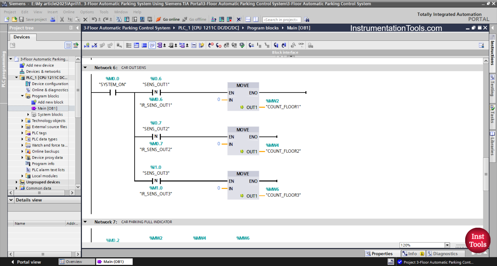
RUNG 6 (CAR OUT SENS)
In this Rung, the value in the memory word COUNT_FLOOR1 (MW2) will decrease (-1) when the NO contact of the memory bit SYSTEM_ON (M0.0) and the SENS_OUT1 (I0.6) sensor are in the HIGH state. Because it uses the Decrement instruction.
When the SENS_OUT2 (I0.7) sensor is in the HIGH state, the value in the memory word COUNT_FLOOR2 (MW4) will decrease by (-1). Because it uses the Decrement instruction.
And, the value in the memory word COUNT_FLOOR3 (MW6) will decrease by (-1) when the SENS_OUT3 (I1.0) sensor is in the HIGH state. Because it uses the Decrement instruction.
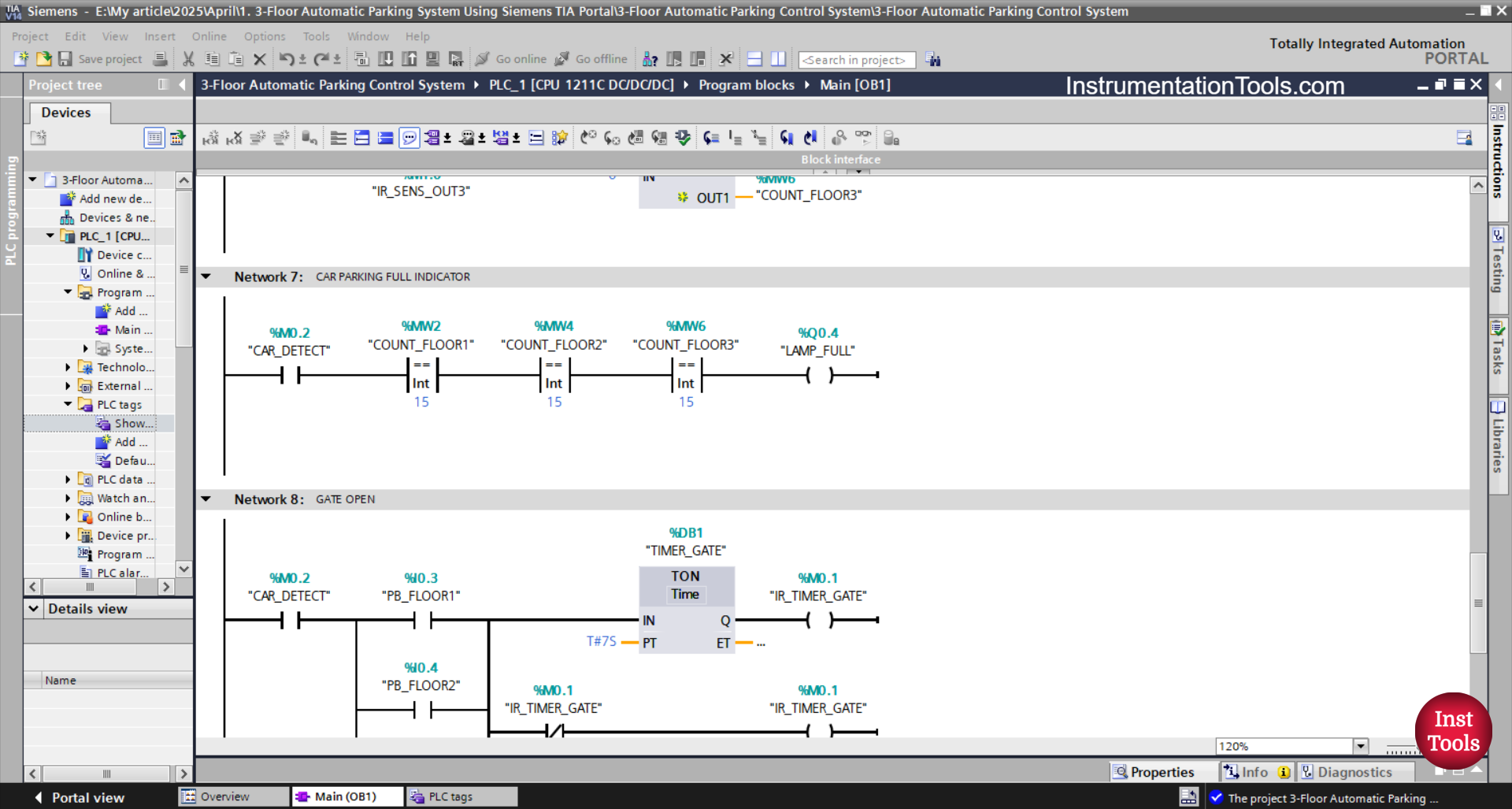
RUNG 7 (CAR PARKING FULL INDICATOR)
If the NO contact of the memory bit CAR_DETECT (M0.2) is in the HIGH state and the value of the memory words COUNT_FLOOR1 (MW2), COUNT_FLOOR2 (MW4), and COUNT_FLOOR3 (MW6) is Equal To “15”, then the output LAMP_FULL (Q0.4) will be ON.
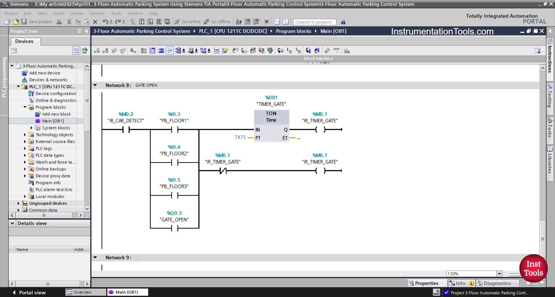
RUNG 8 (GATE OPEN)
The output GATE_OPEN (Q0.3) will be ON when the NO contact of the memory bit CAR_DETECT (M0.2) is in the HIGH state and any of the buttons PB_FLOOR1 (I0.3), PB_FLOOR2 (I0.4), or PB_FLOOR3 (I0.5) is pressed.
The TIMER_GATE (DB1) timer will start counting up to 7 seconds. When the TIMER_GATE (DB1) timer has finished counting.
Even if any of the buttons PB_FLOOR1 (I0.3), PB_FLOOR2 (I0.4), PB_FLOOR3 (I0.5) have been released, the GATE_OPEN (Q0.3) will remain ON. Because it uses Latching.
When the TIMER_GATE (DB1) timer has finished counting, the GATE_OPEN(100.03) output will be OFF because the NC contact of the memory bit IR_TIMER_GATE (M0.1) is in the HIGH state.
Read Next:
- Gas Monitoring Logic with Siemens PLC
- Top Common Causes for PLC System Failure
- Siemens TIA Portal: Oven Control with Conveyor
- Paint Mixing System Control Program using TIA-Portal
- How to Download WPLSoft? Delta PLC Software