When intelligent devices are not communicating or show abnormal status for any reason the DD file often get blamed first. However, the DD file is usually not the problem so time is lost.
Indeed an EDDL file cannot fail. If the problem is a missing DD file, the system will display an error message saying the DD file is missing. If there is no such error message, the problem is something else. This guide provides hints for troubleshooting HART, FOUNDATION fieldbus, PROFIBUS, and other digital communication.
Troubleshoot from the ground up, starting with power supply, then communication, and lastly system integration, and application configuration.
Look for patterns: is it affecting only a single device, many, all devices connected to the same field junction box, or a particular product in many places in the plant? The first generation of some products have had high failure rate but new product design are more reliable.
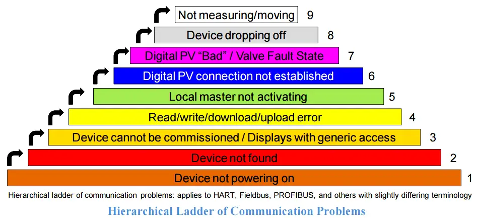
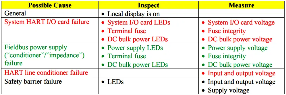
Device Not Powering On
FOUNDATION fieldbus devices need 9 VDC to operate. 4-20 mA/HART device voltage depends on the device type; can be as little as 10.5 V or as much as 19 V or more. Refer to device manual. Voltage shall be measured on device terminal when the current is 20 mA.
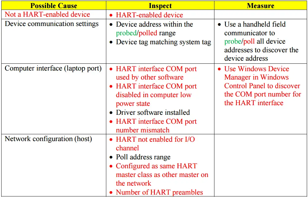
Device Not Found
This refers to the device not being detected and not appearing in the host ‘live list’. Note that even without a DD file loaded on the system a device can still be detected. If the device is not detected, it is not due to missing DD file.
If the system uses the analog 4-20 mA signal typically only address 0 is polled. For multi-drop topology, most systems poll HART address range 1-15. HART7 systems typically set to poll address 1-63. Refer to system manual as each system is different. Make sure HART communication has not been disabled, e.g. due to communication errors.
Fieldbus systems are configured to poll address 16-35 and 232-255 skipping address 36-231. Refer to system manual as the skipped range is slightly different for each system.
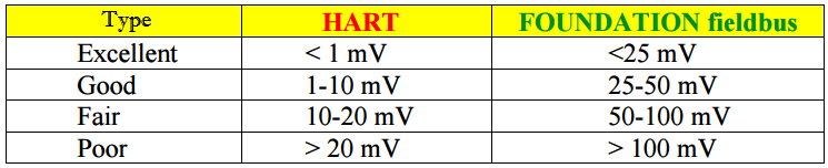
Noise Levels
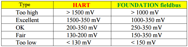
Signal Levels
Displays with Generic Access / Cannot be Commissioned
This refers to when a HART device cannot be displayed with all its internal variables, configuration settings, and diagnostics, or when a fieldbus device cannot be commissioned.
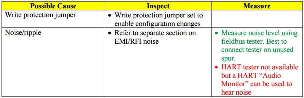
Read / Write / Download / Upload Error
This refers to when a single parameter cannot be changed, configuration download or upload is unsuccessful, or functions such as loop test (simulation), and sensor calibration trim etc. cannot be performed. If fieldbus download is only successful on second or subsequent attempt this is due to internal parameter dependencies – problem common in older device versions but not in new devices and systems supporting “error free download” feature. If HART communication is slow this could be due to burst communication being used by the device.
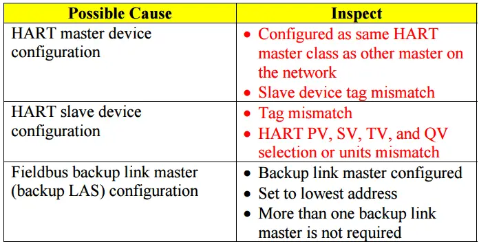
Local Master Not Activating
This refers to when a field device is a HART master polling other HART field devices for information, or a Fieldbus device is a backup Link Master (backup LAS). Connect a portable host to check the device.
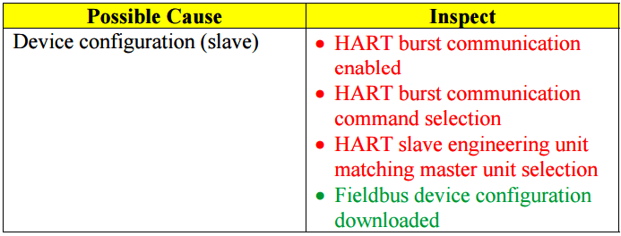
Digital PV Connection Not Established
This refers to problems establishing an individual digital signal link such as PV while the overall device communication is OK. For HART this applies to use of the digital PV and digital valve SP (not 4-20 mA) and includes both burst communication and continuous polling between a slave device and a smart signal conditioner or a control system (e.g. in multi-drop topology). For fieldbus this applies to publishing function block links.
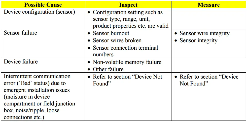
Digital PV Has ‘Bad’ Status / Valve Fault State
This refers to when a digital PV connection is established but the status is ‘Bad’. Make sure to use the Intelligent Device Management (IDM) software to verify the device configuration and diagnostics etc. This may cause a digital valve to trip to fault state. For HART this applies to use of the digital PV and digital valve SP (not 4-20 mA) and includes both burst communication and continuous polling between a slave device and a smart signal conditioner or a control system (e.g. in multi-drop topology). HART digital PV may be interrupted if large data sets like valve signature or radar echo curve is uploaded. For fieldbus this applies to publishing function block links. Many of these causes are not related to digital networking.
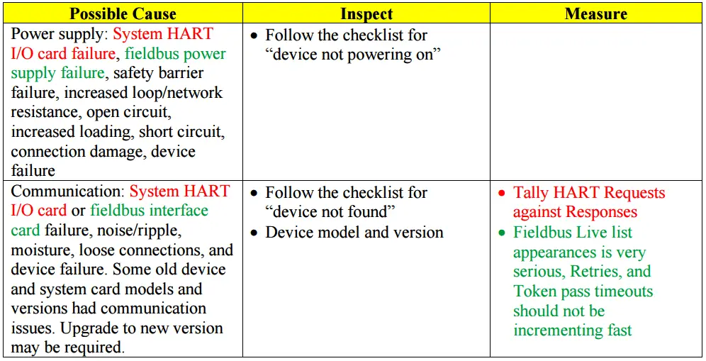
Device Dropping Off
This refers to when a device has been communicating but stops communicating, “drops off”, either permanently or intermittently. The system will display and log an error message. This happens when the system has tried unsuccessfully three times in a row to communicate with the device. Communication statistics in the host diagnostics is a good way to quantify the severity of the problem. If not built into the system, use external bus analyzer software.
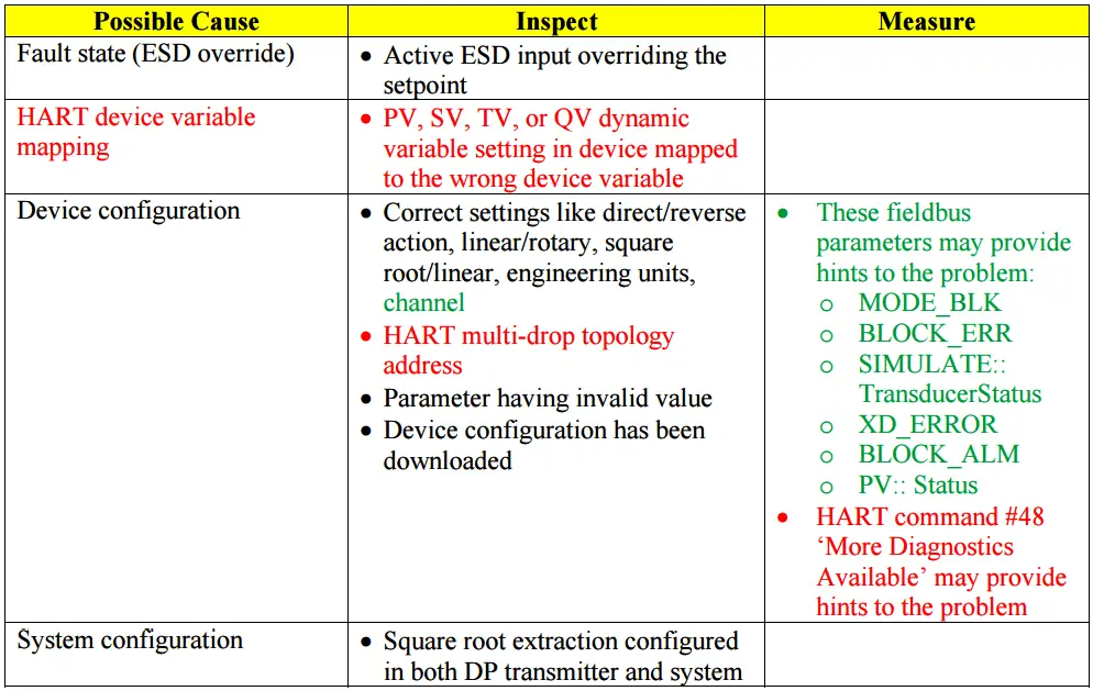
Device Not Measuring / Moving Correctly
The device is communicating, but is not performing its function such as measuring or actuating correctly. For instance, the wrong value may be produced or valve movement is not correct. Many of these causes are not related to digital networking.
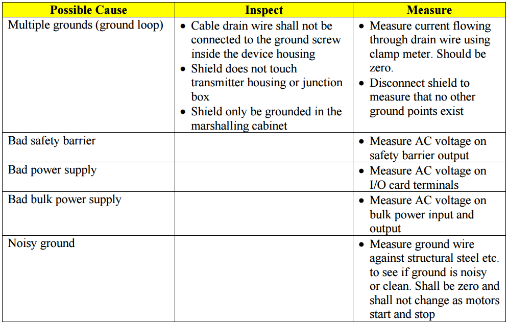
EMI/RFI Noise and Ripple
Excessive noise can interfere with digital communications. The interference may prevent a field device from “hearing” a request from the host system or prevent the host system from “hearing” the response from the field device. Missed messages can cause alarms in the host system and if they persist can lead the system to believe that the device is no longer connected. Similarly, multiple missed publications can lead a subscribing field device to believe the signal is no longer available.
Intermittent problems are those most difficult to troubleshoot. If problems come and go, refer to system error logs and note the time and duration of the errors. Try to correlate the times of these errors with other events such as start and stop of a pump motor or other heavy electric equipment that may cause noise. A fieldbus tester with “peak noise” function can also be used to capture intermittent noise. Signal tester for HART communication is not available but bus analyzer software can be used to capture intermittent communication errors.
Avoid sources of noise
Check that the installation is avoiding sources of noise
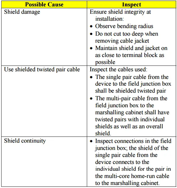
Ensure rejection of noise
Check that the installation ensures rejection of noise
Source : EDDL.org