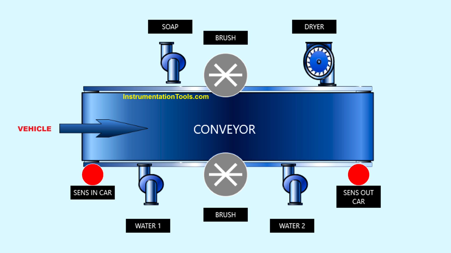
This article will discuss automatic vehicle washing using the XG5000 software-based PLC project. This PLC system operates automatically, managing the stages of water and soap spraying, brushing, rinsing, and drying the car. The system will provide an alarm indicator when the entire process is complete.
Program Objective
System Steps:
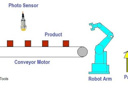
- Vehicle Entry Detection
- Sensors detect a car entering the washing area.
- The conveyor starts moving to transport the car through the washing area.
- Initial Water Spraying
- The water pump activates to evenly wet the car.
- Soap Application and Cleaning
- The soap pump activates to spray cleaning solution onto the car.
- The brush motor starts rotating to scrub and clean the car.
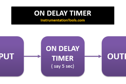
- A timer is used to ensure the washing process is completed within a specific duration.
- Water Rinsing
- After the brushing process is complete, the water pump activates again to rinse Off the soap.
- Drying Stage
- After rinsing is complete, the dryer turns On for a few seconds to dry the car.
- An alarm turn On to notify the driver that the process is finished.
- Vehicle Exit
- After the process is complete, the conveyor stops moving.
- Returning to Initial Position
- All systems shut down and reset, ready for the next vehicle.
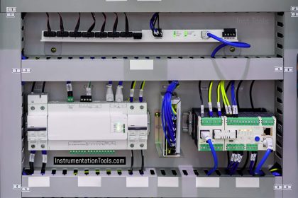
Vehicle Washing PLC Project

IO Mapping
| S.No. | Comment | Input (I) | Output (Q) | Memory Bit | Timer |
|---|---|---|---|---|---|
| 1 | PB_START | P0000 | |||
| 2 | PB_STOP | P0001 | |||
| 3 | SENS_CAR_IN | P0002 | |||
| 4 | SENS_CAR_OUT | P0003 | |||
| 5 | WATER_PUMP1 | P0040 | |||
| 6 | SOAP_PUMP | P0041 | |||
| 7 | CONVEYOR | P0042 | |||
| 8 | MOTOR_BRUSH | P0043 | |||
| 9 | DRYER | P0044 | |||
| 10 | ALARM | P0045 | |||
| 11 | WATER_PUMP2 | P0046 | |||
| 12 | TIMER_WATER1 | T000 | |||
| 13 | TIMER_SOAP | T001 | |||
| 14 | TIMER_BRUSH | T002 | |||
| 15 | TIMER_DRYER | T003 | |||
| 16 | TIMER_WATER2 | T004 | |||
| 17 | TIMER_ALARM | T005 | |||
| 18 | SYSTEM_ON | M0000 |
Program Explained

RUNG 1 (START SYSTEM)
In this rung, if the PB_START (P0000) button is Pressed, the memory bit SYSTEM_ON (M0000) will be in the HIGH state. Because it uses Latching, the memory bit SYSTEM_ON (M0000) will remain in the HIGH state even though the PB_START (P0000) button has been Released.
The memory bit SYSTEM_ON (M0000) will return to the LOW state when the PB_STOP (P0001) button is Pressed.
RUNG 6 (CONVEYOR ON)
In this Rung, when the NO contact of the memory bit SYSTEM_ON (M0000) and the SENS_CAR_IN (P0002) sensor are in the HIGH state, the CONVEYOR (P0042) output will be ON. Because it uses the SET Coil instruction, the CONVEYOR (P0042) output will remain ON even though the NO contact of the memory bit SYSTEM_ON (M0000) or the SENS_CAR_IN (P0002) sensor is in the LOW state.
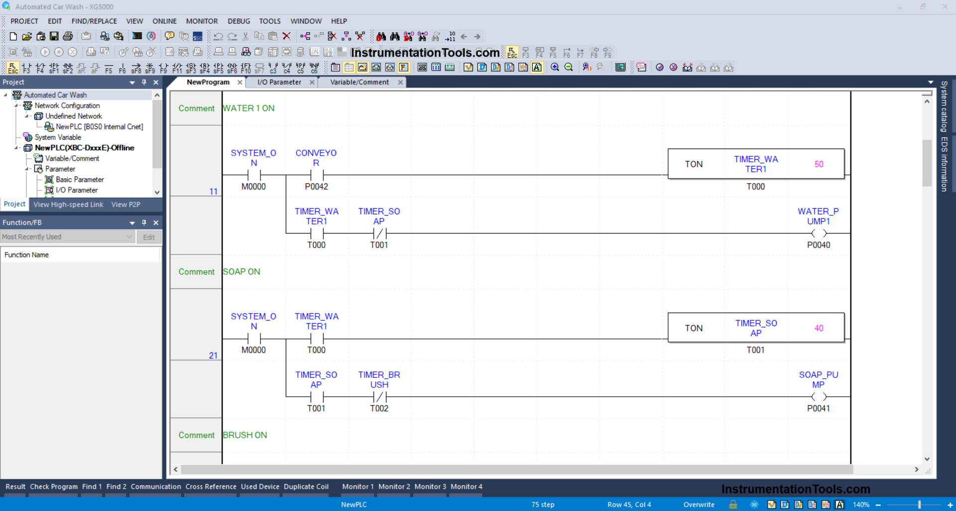
RUNG 11 (WATER 1 ON)
In this Rung, when the NO contacts of the memory bit SYSTEM_ON (M0000) and CONVEYOR (P0042) are in the HIGH state, the TIMER_WATER1 (T000) timer will start counting up to 5 seconds. After the TIMER_WATER1 (T000) timer has finished counting, the WATER_PUMP1 (P0040) output will be ON.
The WATER_PUMP1 (P0040) output will be OFF when the NC contact of the TIMER_SOAP (T001) timer has become a HIGH state.
RUNG 21 (SOAP ON)
In this Rung, when the NO contact of the memory bit SYSTEM_ON (M0000) and the TIMER_WATER1 (T000) timer are in the HIGH state, the TIMER_SOAP (T001) timer will start counting up to 4 seconds. After the TIMER_SOAP (T001) timer has finished counting, the SOAP_PUMP1 (P0041) output will be ON.
The SOAP_PUMP1 (P0041) output will be OFF when the NC contact of the TIMER_BRUSH (T002) timer has become a HIGH state.
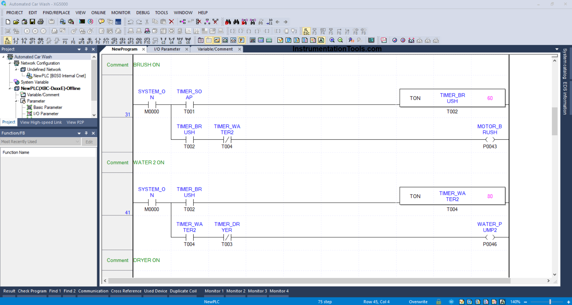
RUNG 31 (BRUSH ON)
In this Rung, when the NO contact of the memory bit SYSTEM_ON (M0000) and the TIMER_SOAP (T001) timer are in the HIGH state, the TIMER_BRUSH (T002) timer will start counting up to 6 seconds. After the TIMER_BRUSH (T002) timer has finished counting, the MOTOR_BRUSH (P0043) output will be ON.
The MOTOR_BRUSH (P0043) output will be OFF when the NC contact of the TIMER_WATER2 (T004) timer has become a HIGH state.
RUNG 41 (WATER 2 ON)
In this Rung, when the NO contact of the memory bit SYSTEM_ON (M0000) and the TIMER_BRUSH (T002) timer are in the HIGH state, the TIMER_WATER2 (T004) timer will start counting up to 8 seconds. After the TIMER_WATER2 (T004) timer has finished counting, the WATER_PUMP2 (P0046) output will be ON.
The WATER_PUMP2 (P0046) output will be OFF when the NC contact of the TIMER_DRYER (T003) timer has become a HIGH state.
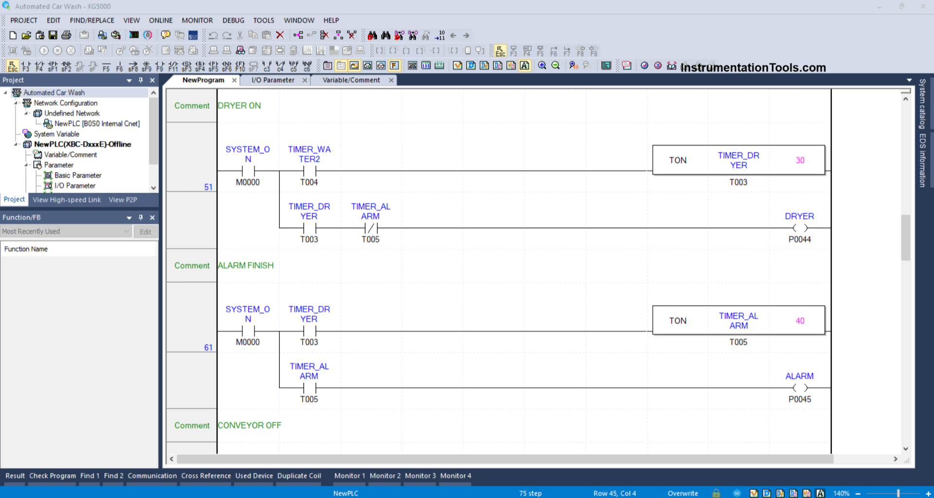
RUNG 51 (DRYER ON)
When the NO contact of the memory bit SYSTEM_ON (M0000) and the TIMER_WATER2 (T004) timer are in the HIGH state, the TIMER_DRYER (T003) timer will start counting up to 3 seconds. After the TIMER_DRYER (T003) timer has finished counting, the DRYER (P0044) output will be ON.
The DRYER (P0044) output will be OFF when the NC contact of the TIMER_ALARM (T005) timer has become a HIGH state.
RUNG 61 (FINISH ALARM)
When the NO contact of the memory bit SYSTEM_ON (M0000) and the TIMER_DRYER (T003) timer are in the HIGH state, the TIMER_ALARM (T005) timer will start counting up to 4 seconds. After the TIMER_ALARM (T005) timer has finished counting, the ALARM (P0045) output will be ON.
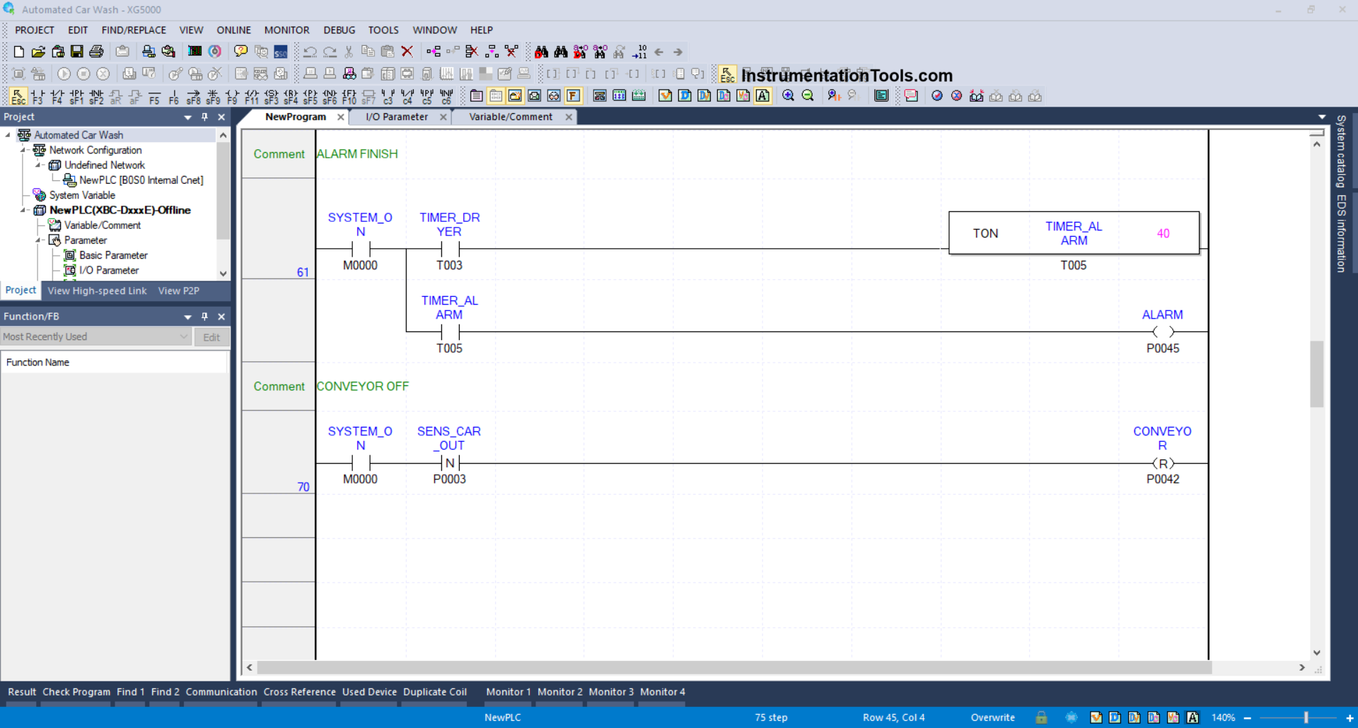
RUNG 70 (CONVEYOR OFF)
In this Rung, because it uses the RESET Coil instruction, the CONVEYOR (P0042) output will be OFF if the NO contact of the memory bit SYSTEM_ON (M0000) and the SENS_CAR_OUT (P0003) sensor are in the HIGH state.
Read Next:
- Smart Street Lighting Using XG5000 PLC Programming
- Escalator Control Based on Passenger Load in PLC
- Read Mitsubishi PLC Analog Input and Display in HMI
- Automated Waste Sorting System Using XG5000 Program
- Communicate Modbus Poll Software with Mitsubishi PLC