This article will explain the manual and automatic garage door control system using the Siemens PLC. The purpose of this system is to provide convenience and safety in operating the garage door through two modes of operation: automatic mode and manual mode. With this system, the garage door can automatically open and close when a vehicle approaches to enter or exit the garage. The system will use the SET Output and RESET Output instructions in the PLC program.
Program Objective
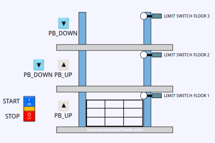
How the System Works:
Mode Selection:
The user can select the garage door operation mode using the selector switch, with the options being Auto (automatic) or Manual mode.
Automatic Mode:
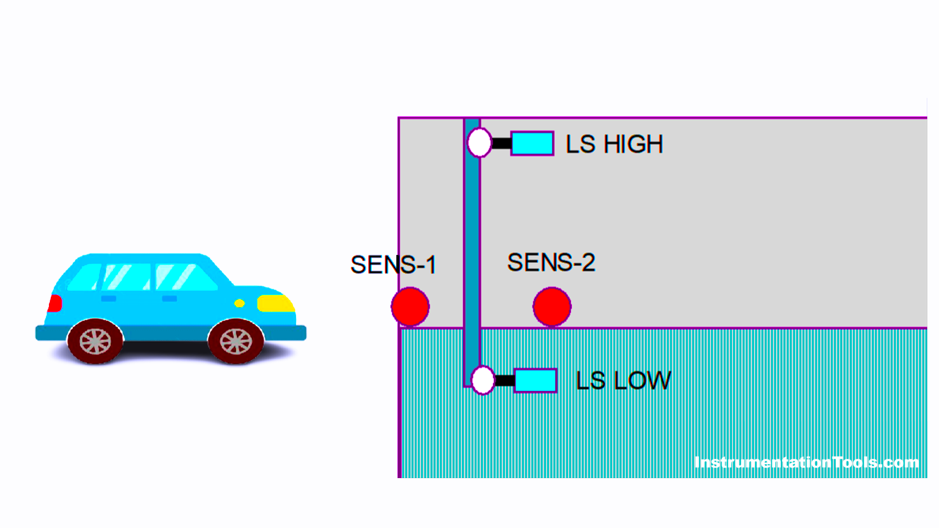
- In automatic mode, the system operates based on input signals from the Limit Switch and Object Sensor. When a vehicle approaches and is detected by the sensor, the system will automatically open the garage door.
- After the vehicle enters or exits, and the sensor no longer detects its presence, the system will automatically close the garage door after a certain delay.
Manual Mode:
- In manual mode, the user can control the garage door directly using the Open or Close button.
- The system will move the door motor according to the command given through the button.
Limit Switch:
- The Limit Switch functions to provide feedback to the system regarding the position of the garage door, whether it is fully open or fully closed.
- This signal is used by the system to regulate the door’s movement, ensuring the door stops at the correct position, whether fully open or fully closed.
IO Mapping Details
| S.No. | Comment | Input (I) | Output(Q) | Memory Bit |
| 1 | PB_START | I0.0 | ||
| 2 | PB_STOP | I0.1 | ||
| 3 | AUTO_MANUAL | I0.2 | ||
| 4 | PB_OPEN | I0.3 | ||
| 5 | PB_CLOSE | I0.4 | ||
| 6 | SENS_1 | I0.5 | ||
| 7 | SENS_2 | I0.6 | ||
| 8 | LS_LOW | I0.7 | ||
| 9 | LS_HIGH | I1.0 | ||
| 10 | DOOR_OPEN | Q0.0 | ||
| 11 | DOOR_CLOSE | Q0.1 | ||
| 12 | SYSTEM_ON | M0.0 | ||
| 13 | IR1_DOOR_OPEN | M0.1 | ||
| 14 | IR2_DOOR_OPEN | M0.2 | ||
| 15 | IR1_DOOR_CLOSE | M0.3 | ||
| 16 | IR2_DOOR_CLOSE | M0.4 | ||
| 17 | IL_CAR_IN | M0.5 | ||
| 18 | IL_CAR_OUT | M0.6 | ||
| 19 | IR1_SENS_1 | M0.7 | ||
| 20 | IR2_SENS_1 | M1.0 | ||
| 21 | IR1_SENS_2 | M1.1 | ||
| 22 | IR2_SENS_2 | M1.2 | ||
| 23 | TEMP1 | M1.3 | ||
| 24 | TEMP2 | M1.4 | ||
| 25 | TEMP3 | M1.5 | ||
| 26 | TEMP4 | M1.6 |
Siemens PLC Coding
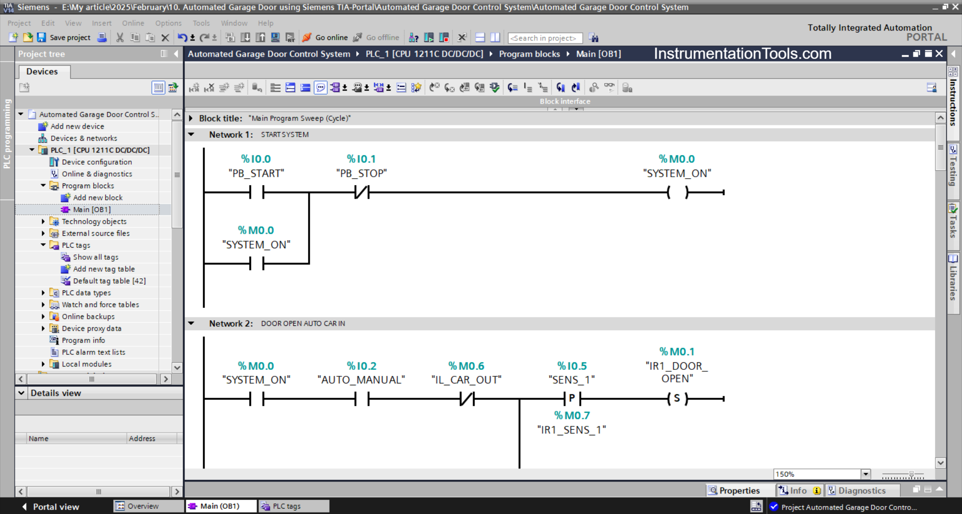
NETWORK 1 (START SYSTEM)
In this network, the memory bit SYSTEM_ON (M0.0) will be in the HIGH state. If the PB_START (I0.0) button is Pressed. Because it uses Latching, the memory bit SYSTEM_ON (M0.0) will remain in the HIGH state even though the PB_START (I0.0) button has been Released.
If the PB_STOP (I0.1) button has been Pressed, the memory bit SYSTEM_ON (M0.0) will return to the LOW state.
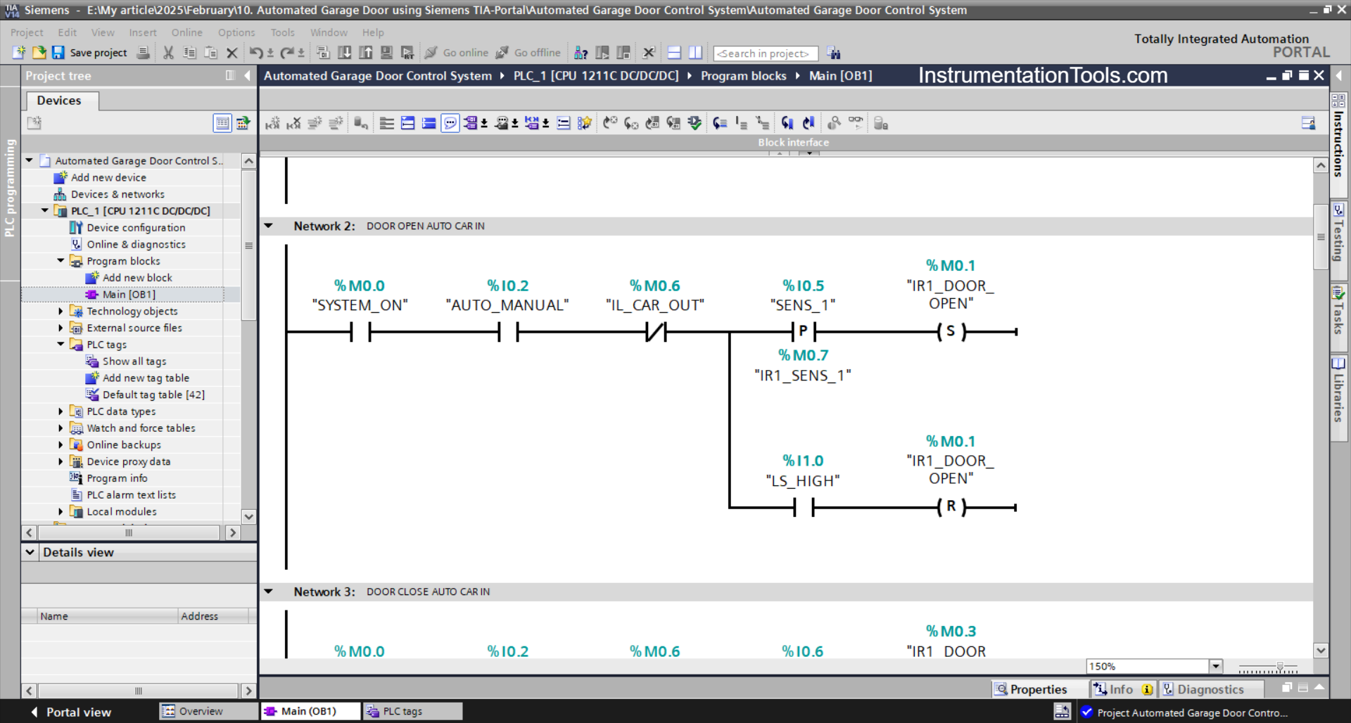
NETWORK 2 (DOOR OPEN AUTO CAR IN)
In this network, if the NO contact of the memory bit SYSTEM_ON (M0.0), selector switch AUTO_MANUAL (I0.2), and sensor SENS_1 (I0.5) are in the HIGH state, then the memory bit IR1_DOOR_OPEN (M0.1) will be in the HIGH state.
When the NO contact of the limit switch LS_HIGH (I1.0) is in the HIGH state, the memory bit IR1_DOOR_OPEN (M0.1) will return to the LOW state. Because it uses the RESET output instruction.
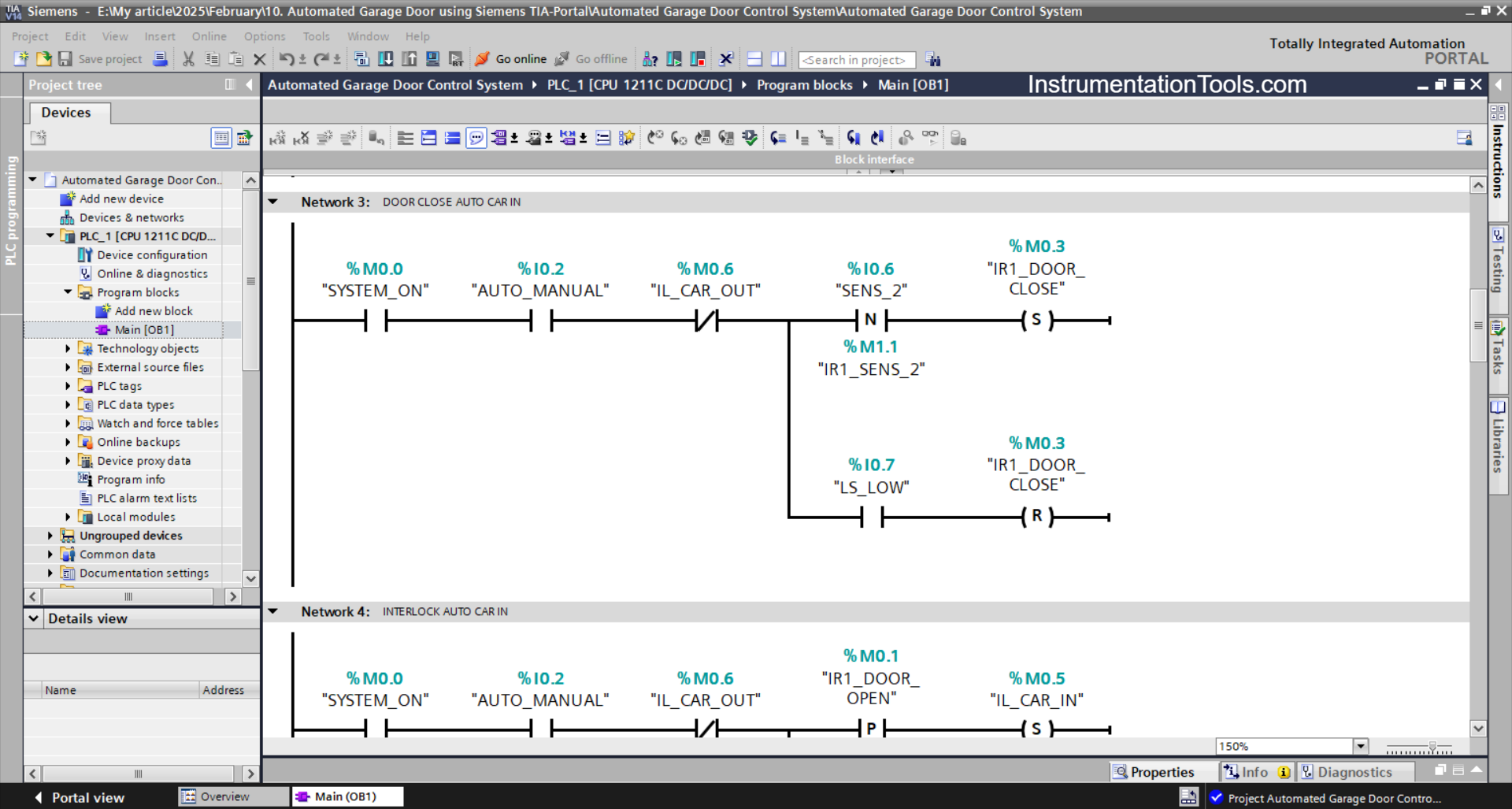
NETWORK 3 (DOOR CLOSE AUTO CAR IN)
In this network, if the NO contacts of the memory bit SYSTEM_ON (M0.0), the AUTO_MANUAL selector switch (I0.2), and the SENS_2 (I0.6) sensor are in the HIGH state, then the memory bit IR1_DOOR_CLOSE (M0.3 will be in the HIGH state.
When the NO contact of the limit switch LS_LOW (I0.7) is in the HIGH state, the memory bit IR1_DOOR_CLOSE (M0.3) will return to the LOW state. Because it uses the RESET output instruction.
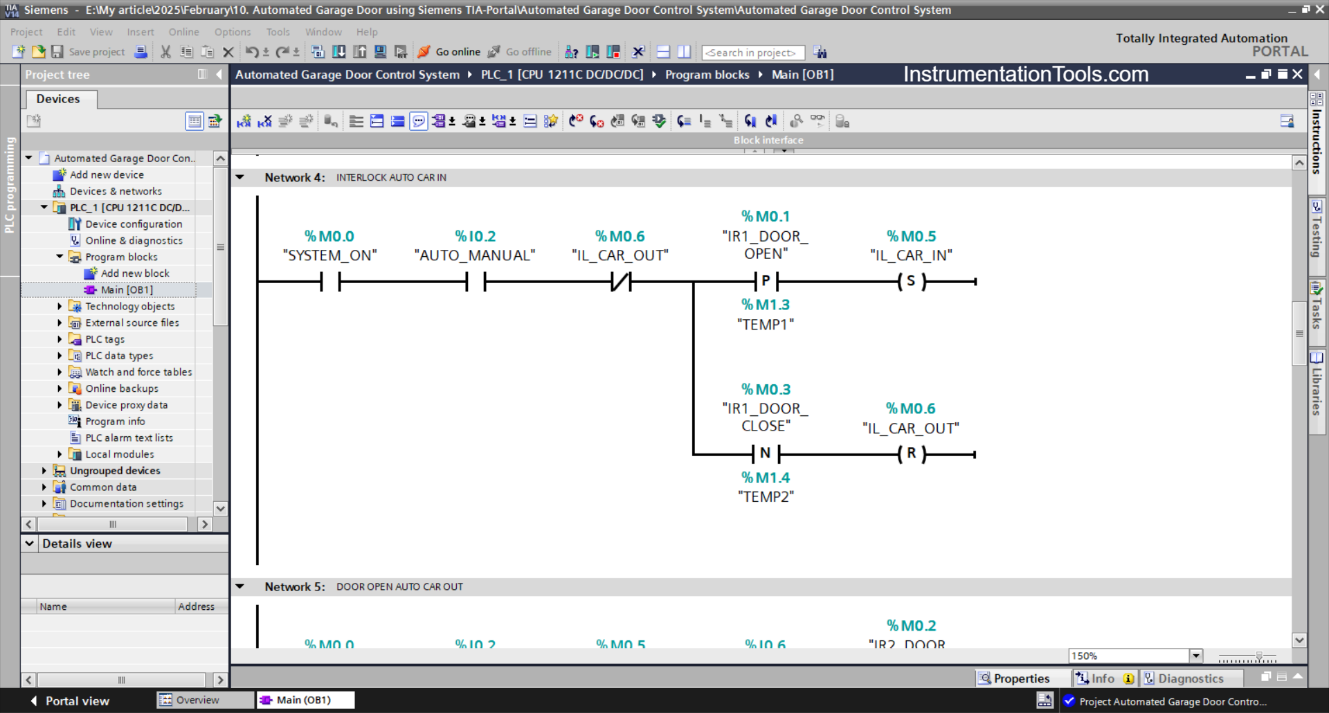
NETWORK 4 (AUTO CAR IN INTERLOCK)
In this network, if the NO contacts of the memory bit SYSTEM_ON (M0.0), IR1_DOOR_OPEN (M0.1), and AUTO_MANUAL (I0.2) are in the HIGH state, then the memory bit IL_CAR_IN (M0.5) will be in the HIGH state.
If the NO contact of the memory bit IR1_DOOR_CLOSE (M0.3) is in the HIGH state, then the memory bit IL_CAR_IN (M0.5) will return to the LOW state. Because it uses the RESET output instruction.

NETWORK 5 (DOOR OPEN AUTO CAR OUT)
In this network, if the NO contact of the bit memory SYSTEM_ON (M0.0), selector switch AUTO_MANUAL (I0.2), and sensor SENS_2 (I0.6) are in the HIGH state, then the memory bit IR2_DOOR_OPEN (M0.2) will be in the HIGH state.
When the NO contact of the limit switch LS_HIGH (I1.0) is in the HIGH state, the memory bit IR2_DOOR_OPEN (M0.2) will be in the LOW state. Because it uses the RESET output instruction.
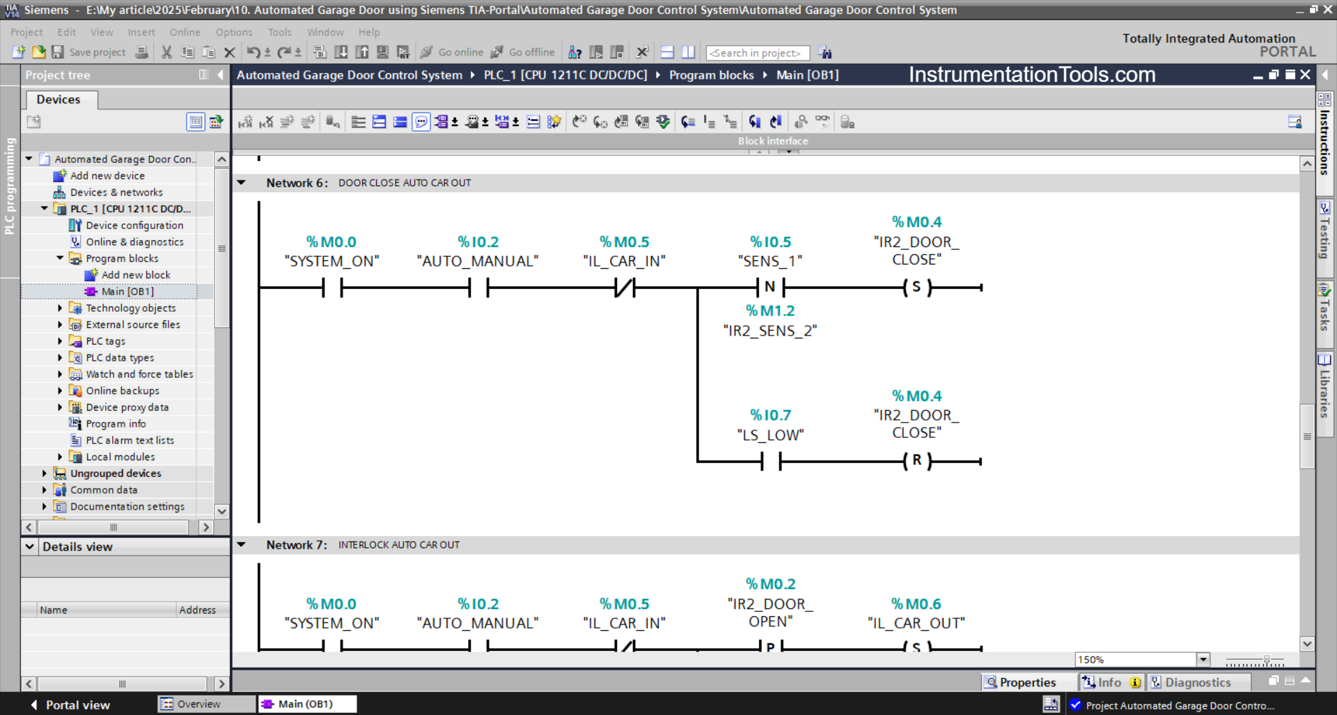
NETWORK 6 (DOOR CLOSE AUTO CAR OUT)
When the NO contact of the memory bit SYSTEM_ON (M0.0) , AUTO_MANUAL selector switch (I0.2), and SENS_1 (I0.5) sensor are in the HIGH state, then the memory bit IR2_DOOR_CLOSE (M0.4) will be in the HIGH state.
The memory bit IR2_DOOR_CLOSE (M0.4) will return to the LOW state if the NO contact of the limit switch LS_LOW (I0.7) is in the HIGH state.
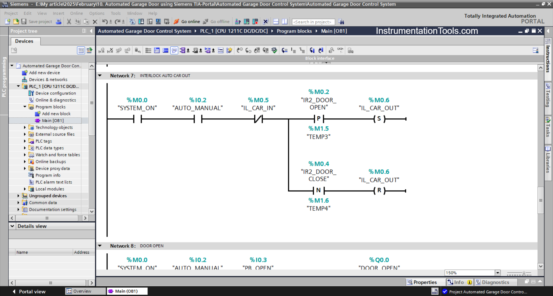
NETWORK 7 (AUTO CAR OUT INTERLOCK)
If the NO contacts of the memory bits SYSTEM_ON (M0.0), IR2_DOOR_OPEN (M0.2), and the selector switch AUTO_MANUAL (I0.2) are in the HIGH state, then the memory bit IL_CAR_OUT (M0.6) will be in the HIGH state.
When the NO contact of the memory bit IR2_DOOR_CLOSE (M0.4) is in the HIGH state, the memory bit IL_CAR_OUT (M0.6) will return to the LOW state.
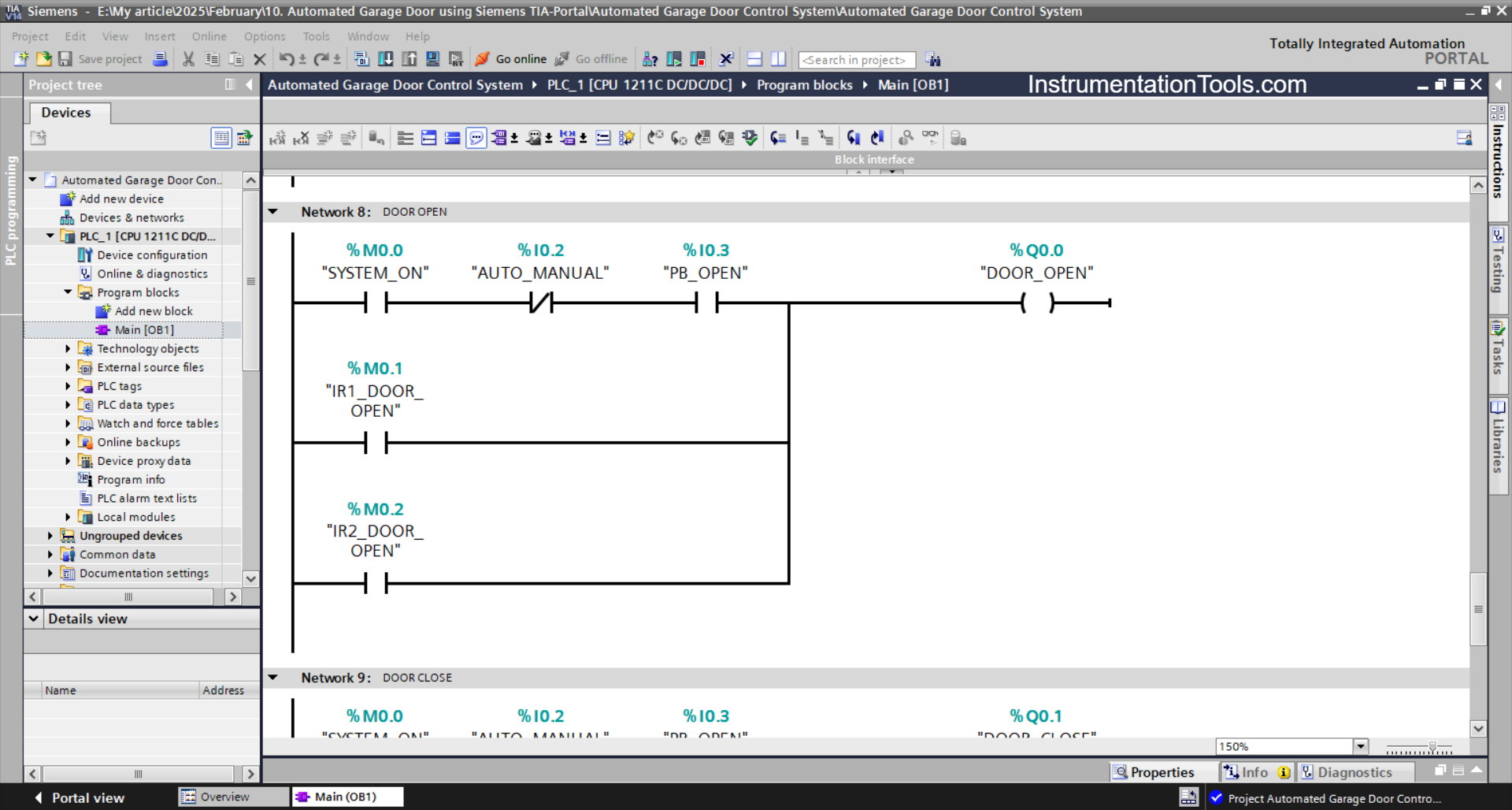
NETWORK 8 (DOOR OPEN)
In this network, when the NO contact of the memory bit SYSTEM_ON (M0.0), and the PB_OPEN (I0.3) button is Pressed, the DOOR_OPEN (Q0.0) output will be ON.
Or, if the NO contact of the memory bits IR1_DOOR_OPEN (M0.1) or IR2_DOOR_OPEN (M0.2) is in the HIGH state, then the output DOOR_OPEN (Q0.0) will be ON.
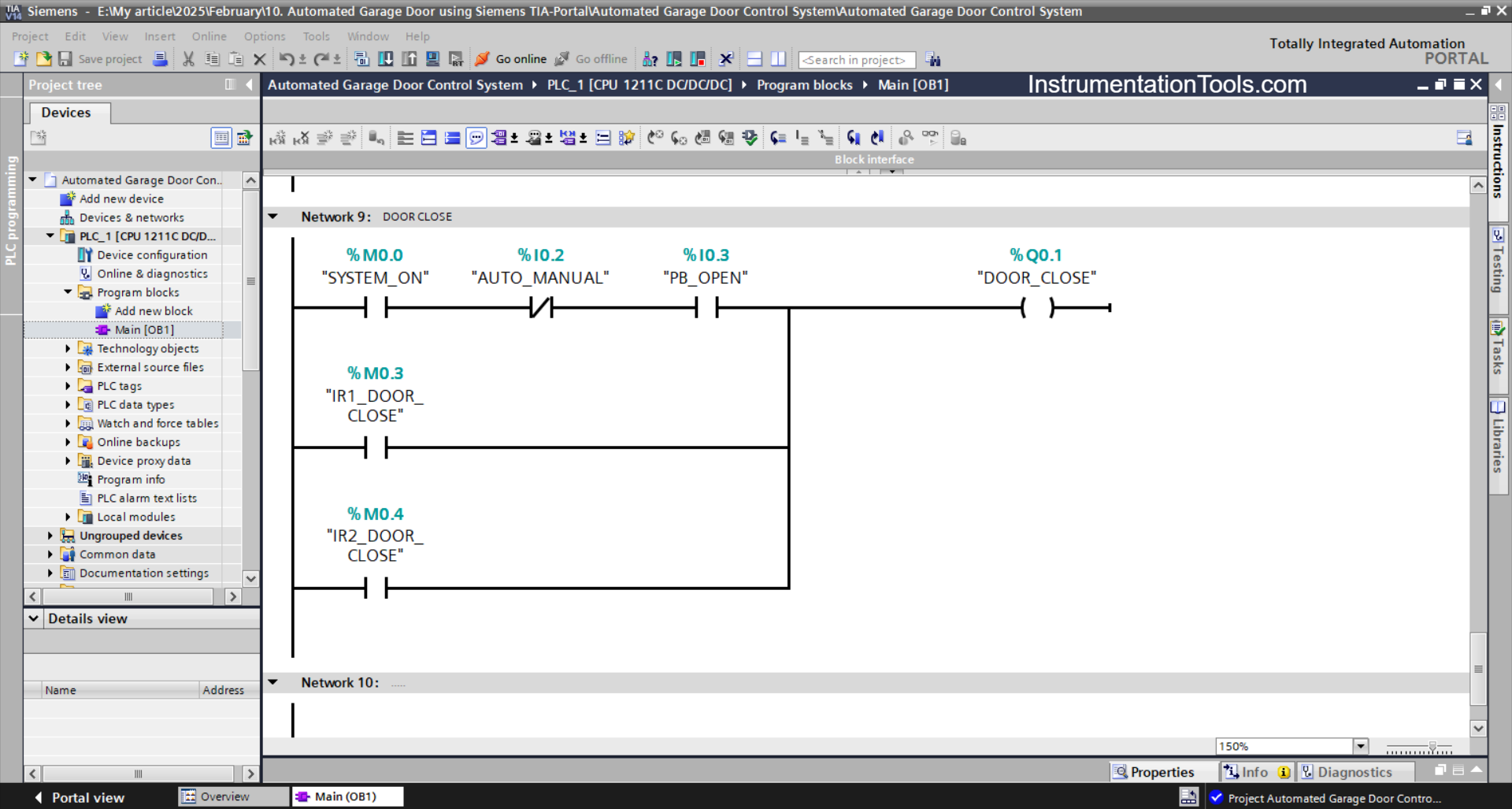
NETWORK 9 (DOOR CLOSE)
In this network, if the NO contact of the memory bit SYSTEM_ON (M0.0), and the PB_CLOSE (I0.4) button is Pressed, then the DOOR_CLOSE (Q0.1) output will be ON.
Or, if the NO contact of the memory bits IR1_DOOR_CLOSE (M0.3) or IR2_DOOR_CLOSE (M0.4) is in the HIGH state, then the output DOOR_CLOSE (Q0.1) will be ON.
Read Next:
- Car Parking System using PLC Programming
- Parking Garage PLC Automation System
- Download GX Works Mitsubishi PLC Software
- Can a PLC Function Without an HMI or SCADA
- Cars Counter From the Same Door PLC Logic