In Today’s engineering world, it is an essential requirement for electrical devices to operate continuously without any disturbance, even though the main power is not available. For this instance only, we are using the Automatic Transfer Switch; this switch will continuously ensure the power to the system by automatically switching between the two power lines. One is the Main power supply line, and the second is the Generator Supply line.
Automatic Transfer Switch (ATS)
The Automatic Transfer Switch does the job for a continuous power supply to the load by taking the power supply either from the Main Power line or the Generator Line. Usually, the load will operate in the Main Power Line only; if there is any fall or failure in the Main Power line means it will automatically take the supply from the generator line. In simple terms, any fault in the Main Line means the load will operate with the help of the Generator line. Once the fault is rectified means then the load will operate with the Main Power line automatically.
This system has minimum disturbances, and we can use it in many crucial applications of industrial plants. This system also ensures the safety of the connections through interlocks that prevent connections of both the main supply and generator line power source. The Major advantage of the system is uninterrupted power supply and is fully automatic, which will save time and process.
Simulation
Components
- 3-Pole Miniature Circuit Breaker (One for Power Line and One for Generator Line)
- 2-Pole Miniature Circuit Breaker (One for Power Line and One for Generator Line)
- Contactors (One for Power Line and One for Generator Line)
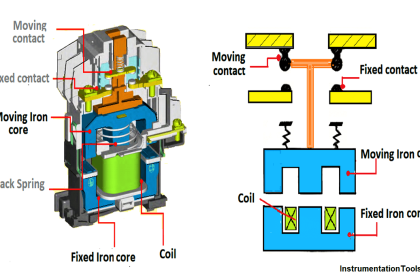
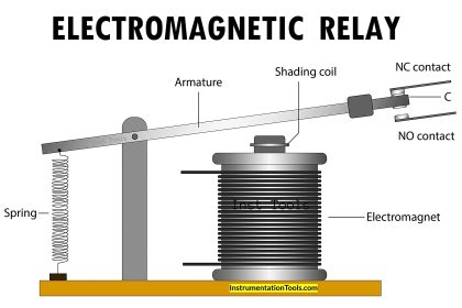
- Relay Coils
- On Delay Timer
- Contactor Coils
- Motor ( Electrical Load)
Circuit Diagram
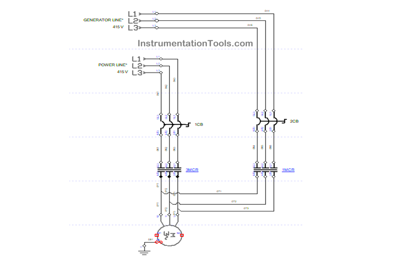
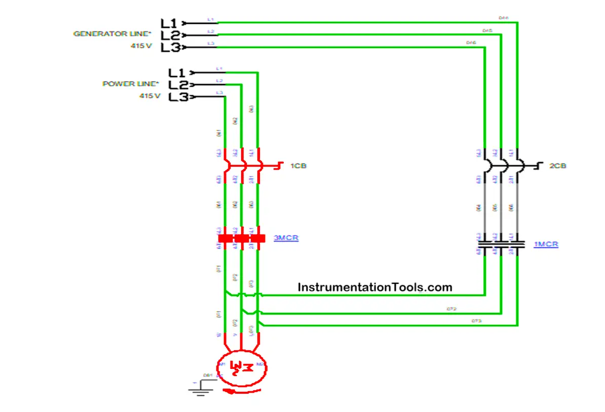
Power Circuit:
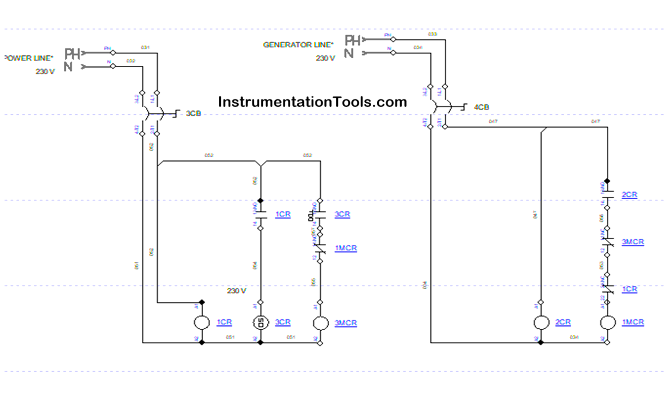
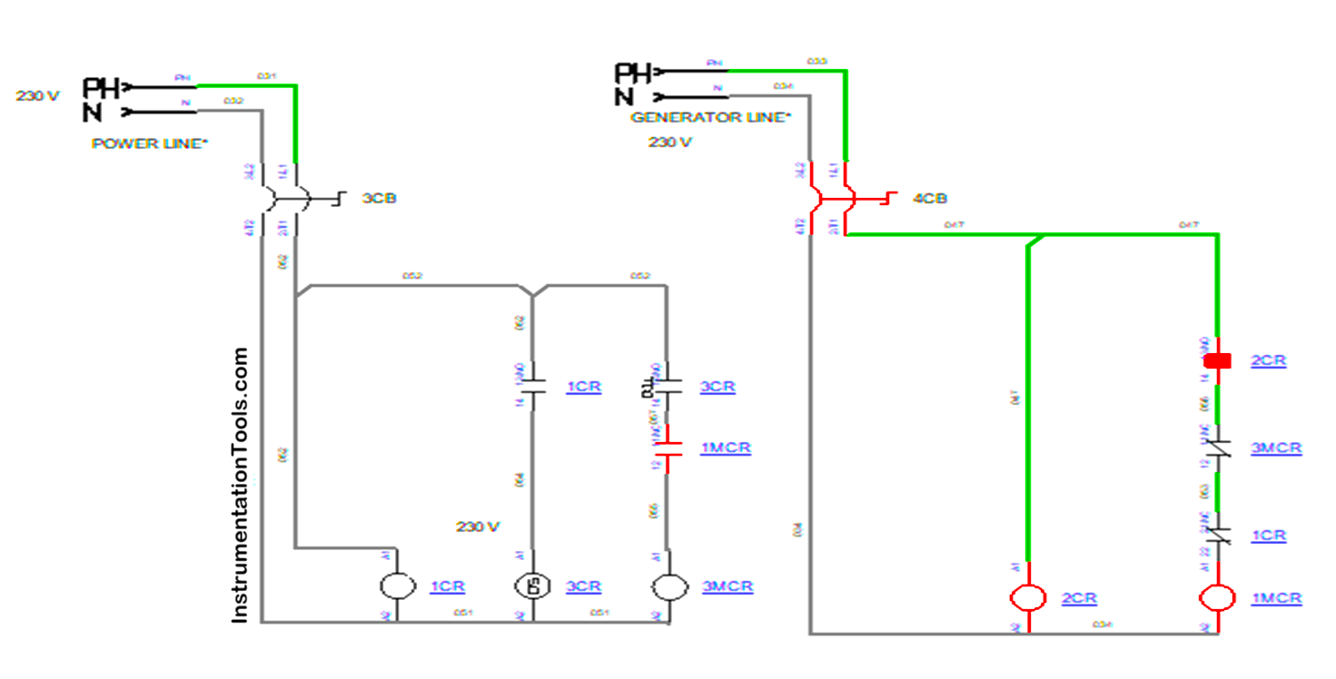
Control Circuit:
Operation of Automatic Transfer Switch
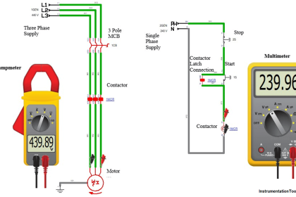
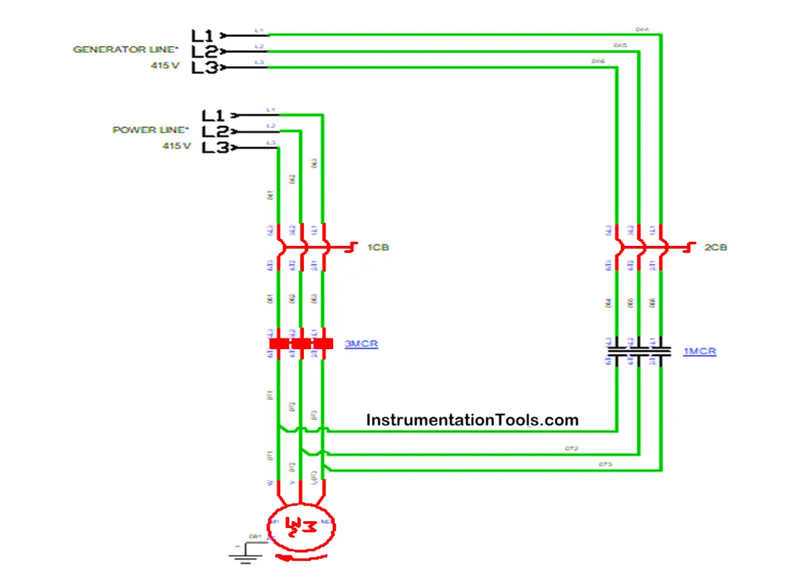
Three-phase supply of 415 V from both the Power Supply Line and the Generator was given to the circuit. Both the supply lines were connected to the separate MCBs, the Power Supply Line was connected to 1 CB, and the Generator line was connected to 2 CBs.
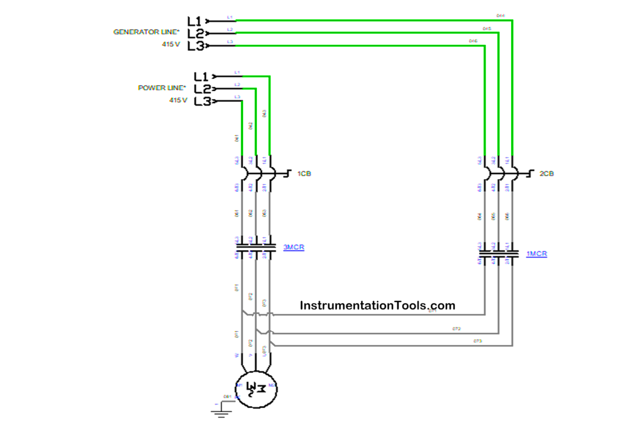
Then both the MCBs were connected to the Contactor, which contacts the load, i.e., the Motor. 1 CB was connected to the contactor 1 (3 MCR), and 2 CB was connected to the contactor 2 (1 MCR).
While operating, both the MCBs 1 CB and 2 CB need to be in the ON condition for the automatic changeover. This completes the Main power circuit of the operation.
Single Phase supply of 230 V was given to the control circuit, likewise Power circuit in the control circuit also we are using two MCBs to control the contactor coils.
Power supply control line is directly connected to the two-pole circuit breaker 2CB, and the Generator line is directly connected to another two-pole circuit breaker 3CB.
The output of circuit breaker 3CB was directly connected to the relay coil 1 CR, timer coil 3CR, contactor coil 3 MCR, and its contacts.
Then the output of circuit breaker 4CB was directly connected to the relay coil 2 CR, contactor coil 1 MCR, and its contacts.
Power Supply of 415 V was given to the circuit breakers 1 CB and 2 CB, and both the MCBs were powered ON in the main circuit
Power Supply of 230 V was given to the circuit breakers 3 CB and 4 CB, and both the MCBs were powered ON in the control circuit.
Because of the power supply given to the circuit breaker, the 3 CB Relay coil 1CR got energized, which makes its contact close and energize the timer 3 CR. The contacts of the timer get closed after 2 2-second of delay.
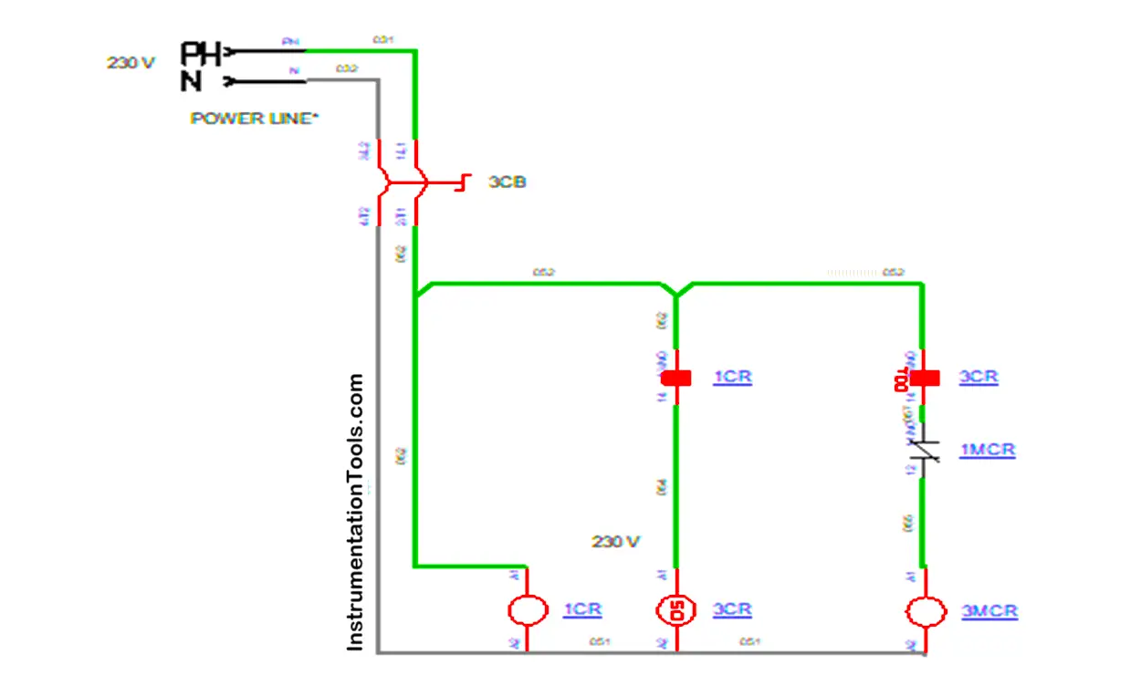
Once the timer contact gets closed, it will activate the contactor coil 3 MCR, which will make the contactor 3 MCR activate and which will energize the load, and the Motor will start rotating.
At the same time, the Generator Line MCB 4CB also turned on, but the contactor coil will not get energized since the normally closed contact of Contactor 3 MCR was connected in series connection.

Once the power is interrupted in the Power Supply line means the generator power will energize the contactor coil 1 MCR, and the motor rotates without stopping because of the continuous supply with the help of the backup generator supply. There will be no time gap or manual operation.
Then, after the Power supply was rectified in the main line, the contactor 3 MCR will get activated and cut the supply to contactor 1 MCR, which means the load will work with the main power supply.
This was the working of this Automatic Transfer Switch, Load will primarily works with Main Power supply line and once the main power was interrupted means the load will work with Generator supply by automatic switch over and then after the clearance of interruptions then the main power supply will be connected automatically with few seconds of delay for smooth transition between the lines.
Conclusion
In this, we have discussed about the Automatic Transfer Switch connection in an Industrial appliance, which provides the uninterrupted power supply in an automatic manner by connecting the load to the power supply line and generator line based on the availability of power. This system is one of the important systems that continuously switch between the main power line and generator line with minimum disturbances. Its automatic function and safety operations make to use in many industries for their continuous operations and work.
Read Next:
- Difference Between MCB and MCCB
- What are Ground Faults and Earth Faults?
- Difference Between MCB and RCBO
- Control Two Motors in Sequence Circuit
- Difference Between Earth and Neutral
- Types of Tripping Protection in MCCB