Inst ToolsInst ToolsInst Tools
  • Courses
  • Automation
    • PLC
    • Control System
    • Safety System
    • Communication
    • Fire & Gas System
  • Instrumentation
    • Design
    • Pressure
    • Temperature
    • Flow
    • Level
    • Vibration
    • Analyzer
    • Control Valve
    • Switch
    • Calibration
    • Erection & Commissioning
  • Interview
    • Instrumentation
    • Electrical
    • Electronics
    • Practical
  • Q&A
    • Instrumentation
    • Control System
    • Electrical
    • Electronics
    • Analog Electronics
    • Digital Electronics
    • Power Electronics
    • Microprocessor
Search
  • Books
  • Software
  • Projects
  • Process
  • Tools
  • Basics
  • Formula
  • Power Plant
  • Root Cause Analysis
  • Electrical Basics
  • Animation
  • Standards
  • 4-20 mA Course
  • Siemens PLC Course
Reading: Ultrasonic Level Transmitter Animation
Share
Notification Show More
Font ResizerAa
Inst ToolsInst Tools
Font ResizerAa
  • Courses
  • Design
  • PLC
  • Interview
  • Control System
Search
  • Courses
  • Automation
    • PLC
    • Control System
    • Safety System
    • Communication
    • Fire & Gas System
  • Instrumentation
    • Design
    • Pressure
    • Temperature
    • Flow
    • Level
    • Vibration
    • Analyzer
    • Control Valve
    • Switch
    • Calibration
    • Erection & Commissioning
  • Interview
    • Instrumentation
    • Electrical
    • Electronics
    • Practical
  • Q&A
    • Instrumentation
    • Control System
    • Electrical
    • Electronics
    • Analog Electronics
    • Digital Electronics
    • Power Electronics
    • Microprocessor
Follow US
All rights reserved. Reproduction in whole or in part without written permission is prohibited.
Inst Tools > Blog > Animation > Ultrasonic Level Transmitter Animation

Ultrasonic Level Transmitter Animation

Last updated: September 14, 2016 6:42 pm
Editorial Staff
Animation How It Works Level Measurement
6 Comments
Share
0 Min Read
SHARE
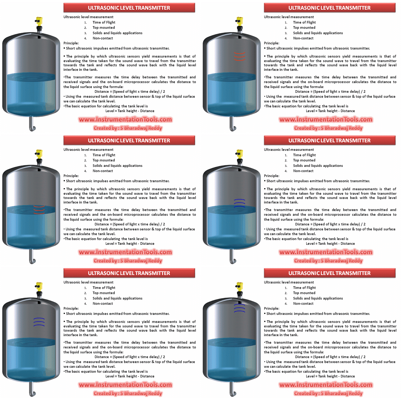
Ultrasonic Level Transmitter Animation

Ultrasonic Level Transmitter Animation shows the working principle of ultrasonic level sensors visually.

Also See :  Ultrasonic Level Transmitter Working Principle


Don't Miss Our Updates
Be the first to get exclusive content straight to your email.
We promise not to spam you. You can unsubscribe at any time.
Invalid email address
You've successfully subscribed !

Continue Reading

All About Instrumentation Impulse Lines
Coriolis Meter Explained with Animation
Spring and Diaphragm Pneumatic Actuators
Advantages & Disadvantages of Level Measurement Systems
Siemens Differential Pressure Transmitter Calculations (Flange Type)
Deluge System for Transformer Protection Animation
Share This Article
Facebook Whatsapp Whatsapp LinkedIn Copy Link
Share
6 Comments
  • Santhosh Kumar says:
    June 4, 2015 at 6:54 pm

    Lovely…Good Animation.

    Reply
  • ruptus gog says:
    September 7, 2015 at 8:37 pm

    WONDERFUL Post.thanks for share..more wait .. …

    Reply
  • Barrett Mena says:
    October 11, 2015 at 7:51 am

    Thanks for sharing your knowledge.

    Reply
  • Keeter says:
    October 17, 2015 at 8:46 am

    This is one awesome post.Really thank you!

    Reply
  • Justin James says:
    July 23, 2019 at 6:31 pm

    An ultrasonic transmitter is being used to measure liquid level in a process vessel. The liquid level in the vessel is 2.8 m. If the transit time of the ultrasonic signal from the sensor to the liquid surface and its return is 8.3 ms, calculate the distance from the sensor to the bottom of the vessel. The velocity of sound through the medium is 342 m/s.

    what will be the answer, which equation needs to be used?

    Reply
  • Ibrahim khleifat says:
    December 21, 2019 at 5:57 pm

    Distance = speed of sound x Td/2 = 342 m/s x 8.3 ms / 2 = 342 m/s x 8.3 x0.001/2 = 342 m/s x0.00415 = 1.42 m

    Tank height = liquid level + distance = 2.8m + 1.42 m = 4.22 m

    Reply

Leave a Reply Cancel reply

Your email address will not be published. Required fields are marked *

Stay Connected

128.3kFollowersLike
69.1kFollowersFollow
208kSubscribersSubscribe
38kFollowersFollow

Categories

Explore More

Hybrid Level Measurement Principle, Selection, Installation, Limitations and Calibration
Stilling Well in Interface Level Measurement System
Open Tank Level Measurement using DP Transmitter
Differential Pressure Level Transmitter Errors
Turbine Flow Meters Animation
Relay Principle & its Types
Hydrostatic Interface Level Measurement
Motor Classic Control Circuits using Single Push button

Keep Learning

hall-effect-sensor

Hall Effect Sensor Working Principle Animation

Control Valve Working Animation

Control Valve Working Animation

Why Measure Level

Pressure Measurement

How to Measure Pressure in Inches of Water Column

How a Level Switch Works

Switched Mode Power Supply (SMPS)

How does SMPS Works? – Switched Mode Power Supply

Guided-wave Radar Level Measurement Animation

Flow Switch Principle

In-Line Flow Switch Working Principle and Animation

Learn More

Types of Engineering Courses

Various Types of Engineering Courses

Maintenance Override Switch (MOS)

What is Maintenance Override Switch (MOS) ?

PLC Program for motor operation based on time cycle

PLC Motor Operation based on Time Cycle Sequence – Program

Components of a Water Treatment Plant

Components of Water Treatment Plant

Differential Pressure Flow Meters

Short Notes on Differential Pressure Flow Meters

Calculate Hydrostatic Pressure of a vertical column of Acetic Acid

Hydrostatic Pressure of a vertical column of Acetic Acid

Blowout preventer (BOP) Principle

Blowout preventer (BOP) Principle

Device Connected to MODEM

Internal Powered Modems

Follow US
All rights reserved. Reproduction in whole or in part without written permission is prohibited.
Welcome Back!

Sign in to your account

Username or Email Address
Password

Lost your password?