Learn how to create a PLC program for a scheduled daily plant watering system using ladder logic.
Scheduled Daily Plant Watering
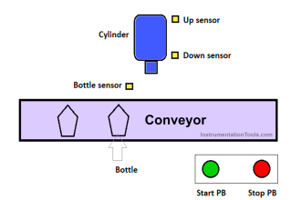
The PLC program is an automation system for watering plants or gardens which will Activate the Water sprinkler at certain time periods. In this program, the water sprinkler will be Active on 2 different schedules.
In the first schedule, the water sprinkler will be Active every Monday (#1) – Saturday (#6) from 09.00 – 09.15. The second water sprinkler schedule will be Active on Sunday (#7) from 08.00-08.30. To be able to RUN both schedules, it is necessary to use the RTC (Real Time Clock) function.
RTC Addressing Memory
In CX-Programmer, Real-time clock (RTC) data processing is allocated in Word memory address A351-A354, each Word memory address contains two RTC time units which are divided into each 8 bits in the form of Data type BCD (Binary code Decimal) and displayed in hexadecimal units. The RTC can calculate units of time from a scale of Seconds to Years.
The table below shows the distribution of Word RTC memory data.
| Word Memory Area | Bit Area | Function | Range Time | Data Type |
| A351 | A351.00 – A351.07 | Seconds | 00 – 59 | BCD |
| A351.08 – A351.15 | Minutes | 00 – 59 | BCD | |
| A352 | A352.00 – A352.07 | Hours | 00 – 23 | BCD |
| A352.08 – A351.15 | Date | 0 – 31 | BCD | |
| A353 | A353.00 – A353.07 | Month | 01 – 12 | BCD |
| A353.08 – A353.15 | Year | 00 – 99 | BCD | |
| A354 | A354.00 – A354.07 | Day of the Week | 00 – 06 (Sunday Saturday) | BCD |
| Not used |
How This PLC Program Works?
The PLC Program has 2 main buttons, the START (0.00) button is used to turn ON the system, and the STOP (0.01) button is used to turn OFF the system. When the system has been activated then the schedule parameters need to be entered in the word memory allocation SET_ON_DAILY_TIME1 (D0-D1), SET_OFF_DAILY_TIME1 (D10-D11), SET_ON_DAILY_TIME2 (D15-D16), SET_OFF_DAILY_TIME1 (D20-D21).
In the first schedule, watering Active time is Monday (#1) – Saturday (#6) hours 09.00-09.15 then the time parameter needs to be Set on Word memory allocation SET_ON_DAILY_TIME1 “D0 = 0000 & D1 = 0009” and SET_OFF_DAILY_TIME1 “D10 = 1500 & D11 = 0009”. Word memory allocation SET_ON_DAILY_TIME1 (D0-D1) serves as the first schedule’s Active Time parameter and SET_OFF_DAILY_TIME1 (D10-D11) serves as the first schedule’s Off Time parameter.
In the second schedule, the watering Active time is on Sunday (#0) hours 08.00-08.30 then the time parameter needs to be Set on the word memory allocation SET_ON_DAILY_TIME2 “D15 = 0000 & D16 = 0008” and SET_OFF_DAILY_TIME1 “D20 = 3000 & D21 = 0008”. Word memory allocation SET_ON_DAILY_TIME2 (D15-D16) serves as the second schedule’s Active Time parameter and SET_OFF_DAILY_TIME2 (D20-D21) serves as the second schedule’s Off Time parameter.
When the first schedule is Active, it will activate the Output GARDEN_SPRINKREL_TIME1 (100.00). When the second schedule is Active, it will Activate the Output GARDEN_SPRINKREL_TIME2 (100.01).
I/O Details
Addressing Input, Output, TIM, Bit Memory, and Word Memory details are as follows.
| Comment | Input (I) | Output(Q) | Word Memory | Memory Bits |
| START | 0.00 | |||
| STOP | 0.01 | |||
| SYSTEM_ON | W0.00 | |||
| GARDEN_SPRINKREL_TIME1 | 100.00 | |||
| GARDEN_SPRINKREL_TIME2 | 100.01 | |||
| RTC_HOUR_MINUTE_SECOND | A351 | |||
| RTC_DAY | A354 | |||
| SET_ON_DAILY_TIME1 | D0 – D1 | |||
| SET_OFF_DAILY_TIME1 | D10 – D11 | |||
| SET_ON_DAILY_TIME2 | D15 – D16 | |||
| SET_OFF_DAILY_TIME2 | D20 – D21 |
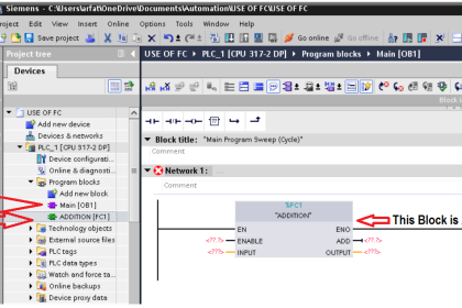
PLC Programming
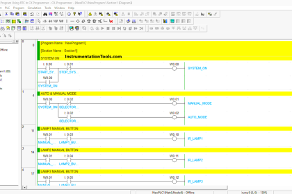
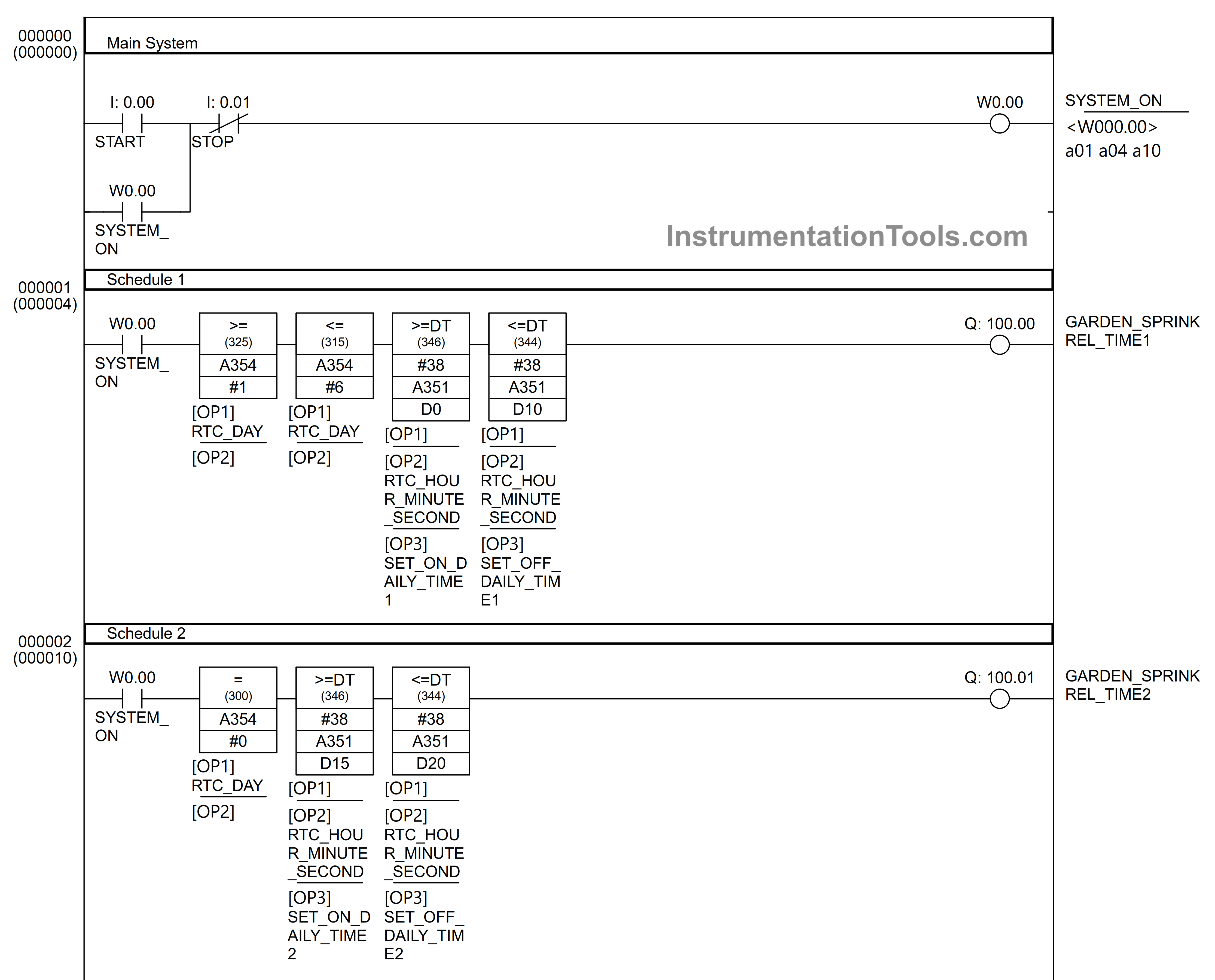
In the figure above, it is shown when the START (0.00) button is pressed, it will activate the memory Bit SYSTEM_ON (W0.00). Because of the latching function, the System_on Bit memory (W0.00) remains Active even though the START button is released.
The Outputs GARDEN_SPRINKREL_TIME1 (100.00) and GARDEN_SPRINKREL_TIME2 (100.01) are still not active because the time parameter on the instruction has not been Set and the instruction condition has not been met.
Because the time parameters Year, Month, and Date are not used, they need to be Disabled by adding Hex number #38 to the Instructions.
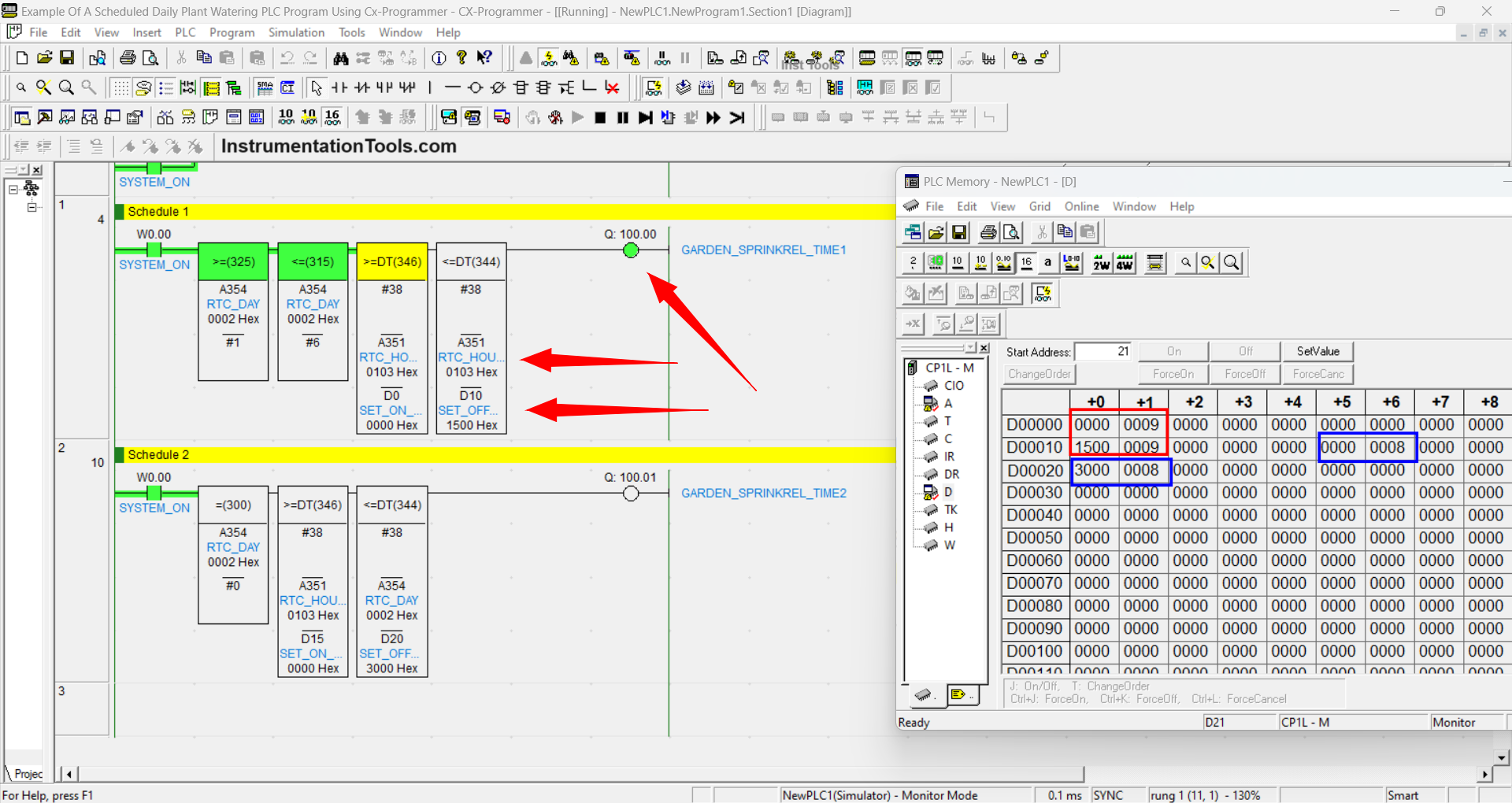
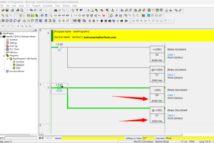
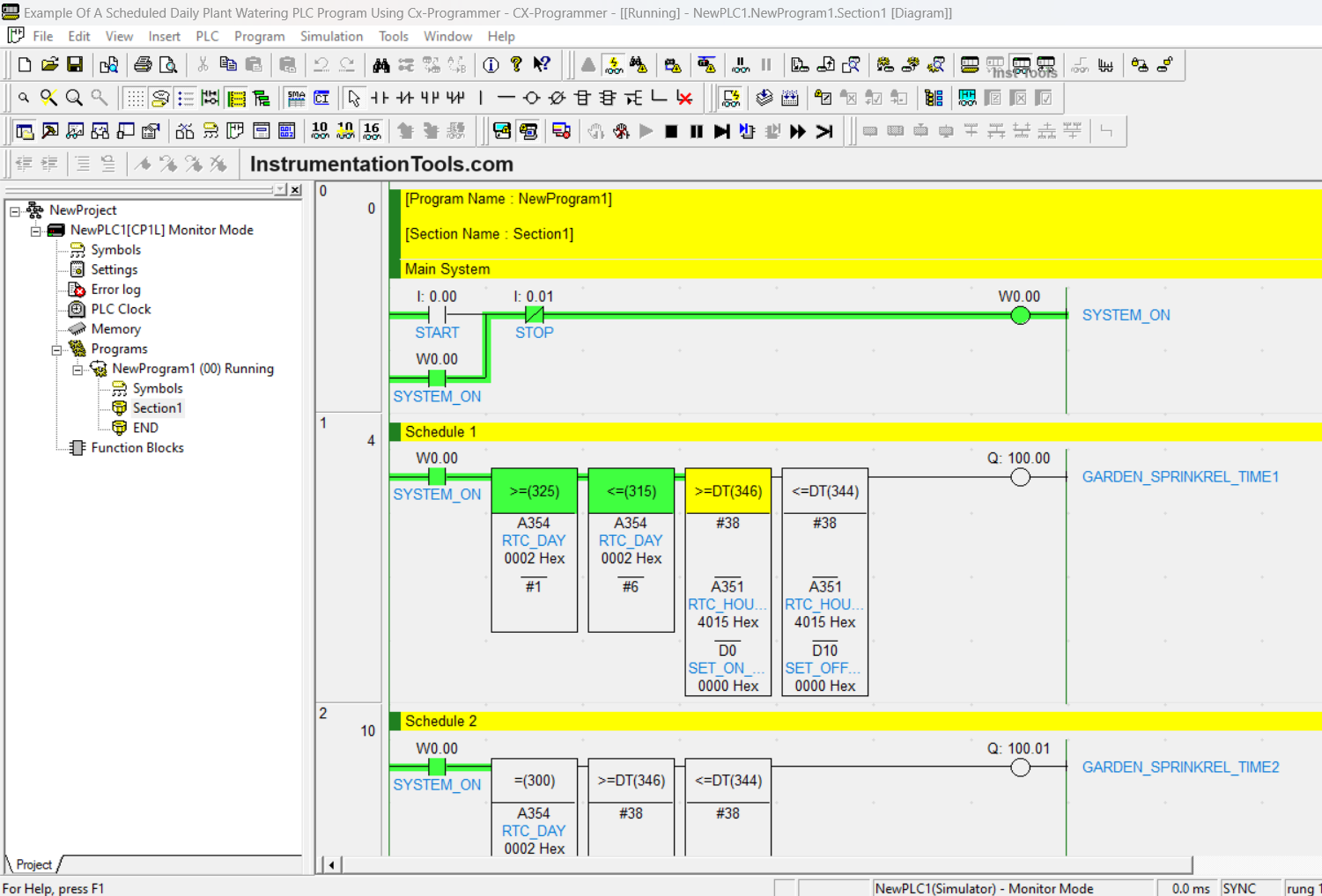
The image above shows the condition when the GARDEN_SPRINKREL_TIME1 (100.00) Output is Active.
It can be seen in the PLC memory Pop-up Window, the first watering schedule time parameters have been entered in the Word memory allocation SET_ON_DAILY_TIME1 “D0 = 0000 & D1 = 0009” and SET_OFF_DAILY_TIME1 “D10 = 1500 & D11 = 0009”.
Because the RTC time has been in accordance with the conditions of the instruction, the Output GARDEN_SPRINKREL_TIME1 (100.00) becomes Active. Output GARDEN_SPRINKREL_TIME1 (100.00) will be Disabled when the RTC time has passed 09.15.
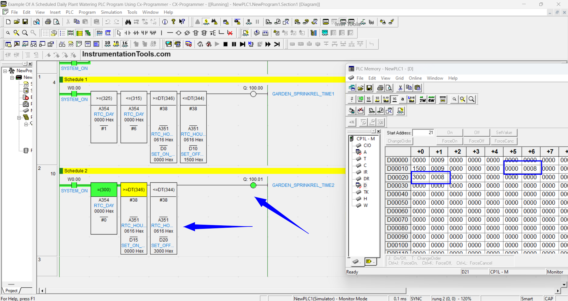
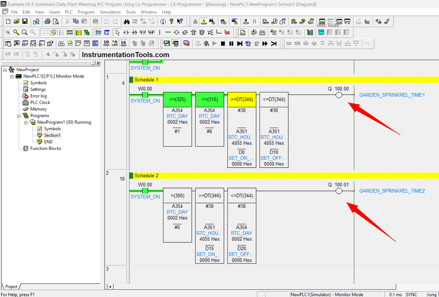
The figure above shows the condition when the Output GARDEN_SPRINKREL_TIME2 (100.01) has been Active. In the Pop-Up window, PLC memory can be seen as the value of the time parameter that has been entered in the word memory allocation SET_ON_DAILY_TIME2 “D15 = 0000 & D16 = 0008” and SET_OFF_DAILY_TIME1 “D20 = 3000 & D21 = 0008”.
The second Schedule will only be Active on Sundays from 08.00-08.30 so that when the time is above 08.30 then the output GARDEN_SPRINKREL_TIME2 (100.01) will be Disabled.
If you liked this article, please subscribe to our YouTube Channel for PLC and SCADA video tutorials.
You can also follow us on Facebook and Twitter to receive daily updates.
Read Next:
- PLC Program for Daily Production Record
- Tagging Philosophy for Junction Box & Cable
- PLC Programming for Boolean Expression Equation
- Shutter Door Control using Motor and Limit Switches
- Concept of Shift Register in Omron PLC with Example