We will discuss the PLC applications examples and one of them is door locking system based on PLC programming logic.
Note: We encourage individuals to use this PLC example for educational purposes to learn the ladder logic with good practical applications.
Door Locking System
Problem Statement:
Design a PLC ladder logic for the following application.
We are using two buttons and one Sensor to control the door-locking system.
When the lock button is pressed, the doors should lock and when the unlock button is pressed, the doors remain unlocked for 10 seconds and then get locked. The doors should not lock if there is someone at the door.
PLC Automation Videos
Instrumentation Tools provides you the free access to the PLC automation videos on our YouTube channel.
The below video explains the door lock and unlock example program.
I/O List
Digital Inputs:
Lock Button: I0.0
Unlock Button : I0.1
Sensor: I0.2
Digital Outputs:
Doors: Q0.0
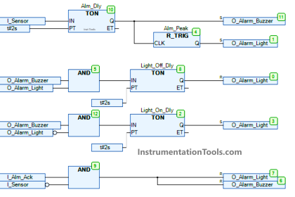
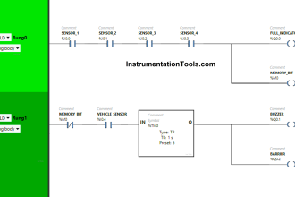
Ladder Logic
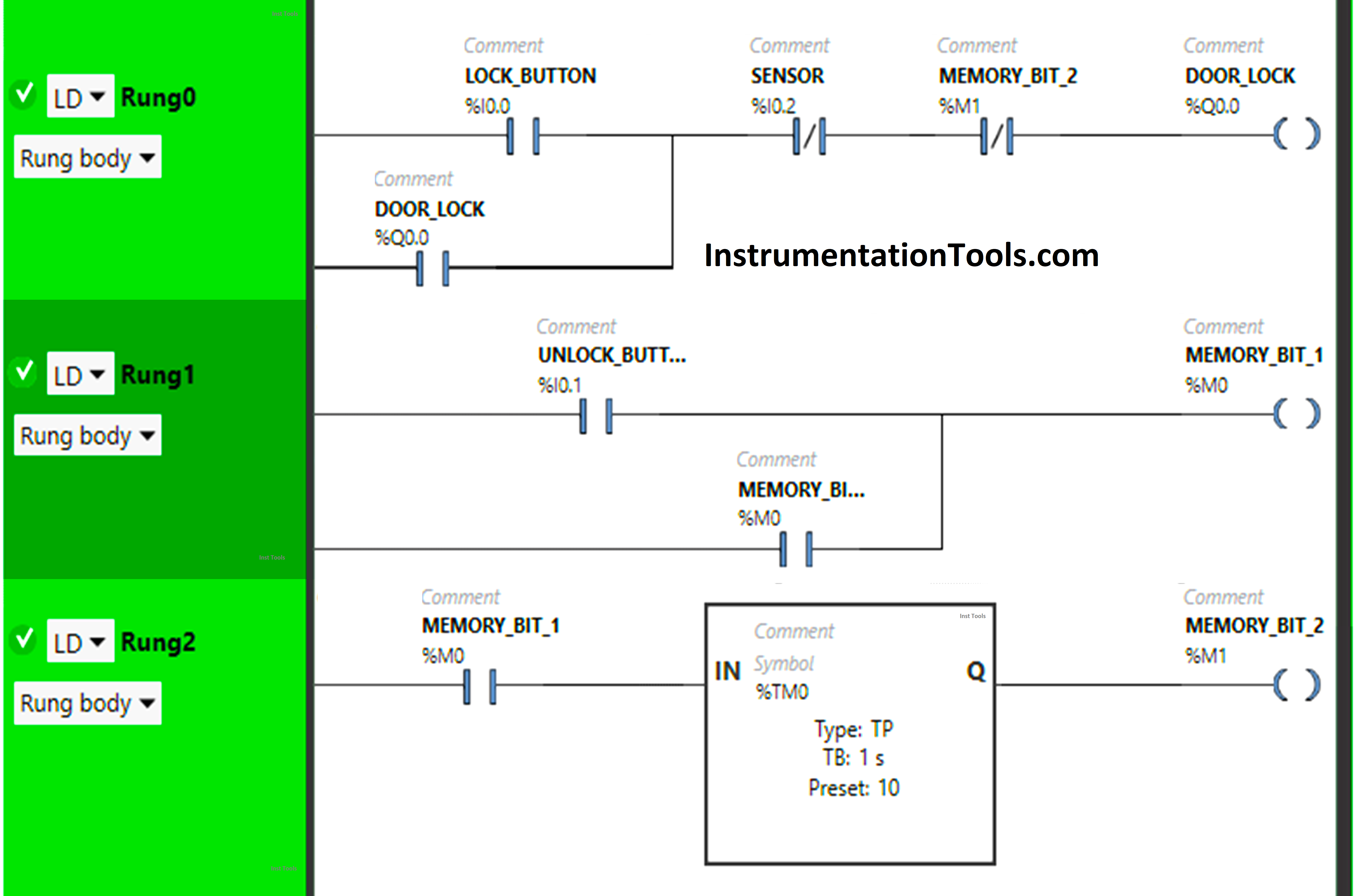
Program Description
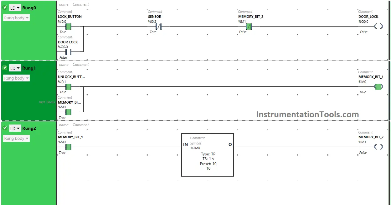
We have used Normally Open Contacts for Lock Button (I0.0), Unlock button (I0.1) and Memory Bits.
We have used Normally Closed Contacts for Sensor (I0.2) and Memory Bit 2 (M1).
In Rung 0:
- Normally Open Contact is used for Lock Button (I0.0) to Turn ON the output Door Lock (Q0.0).
- Normally Closed Contacts are used for Sensor (I0.2) and Memory Bit 2 (M1) to turn OFF the output Door Lock (Q0.0).
- The output Door Lock (Q0.0) is latched so that when Lock Button (I0.0) turns OFF, the output Door Lock (Q0.0) still remains ON.
In Rung 1:
- Normally Open Contact is used for Unlock Button (I0.1) to Turn ON Memory Bit 1 (M0).
- Memory Bit 1 (M0) is latched so that Unlock Button (I0.1) turns OFF, Memory Bit 1 (M0) still remains ON.
In Rung 2:
- Normally Open Contact is used for Memory Bit 1 (M0) to Turn ON Memory Bit 2 (M1).
- Timer TP is used to Turn ON Memory Bit 2 (M1) for limited time.
PLC Logic Simulation
Lets test our PLC logic and check the results.
When Lock Button is Pressed
When Lock Button (I0.0) is pressed, the output Door Lock (Q0.0) turns ON (Doors will Lock) as Normally Open Contact used for Lock Button (I0.0) will be in True state and passes the signal to turn On the output Door Lock (Q0.0).
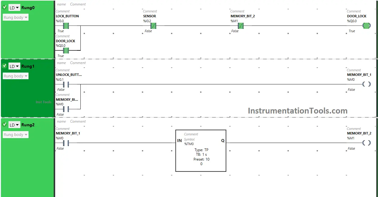
In false state, Normally Closed Contacts used for Sensor (Q0.2) and Memory Bit 2 (M1) will also allow the signal to flow through it and the output (Q0.0) will turn ON (Doors will Lock).
When Unlock Button is Pressed
When Unlock Button (I0.1) is pressed,Lock Unlock Door For Home AutomationMemory Bit 1 (M0) turns ON in Rung1. Memory Bit 1 (M0) is latched so that when Unlock Button (I0.1) turns OFF, Memory Bit 1 (M0) still remains ON.
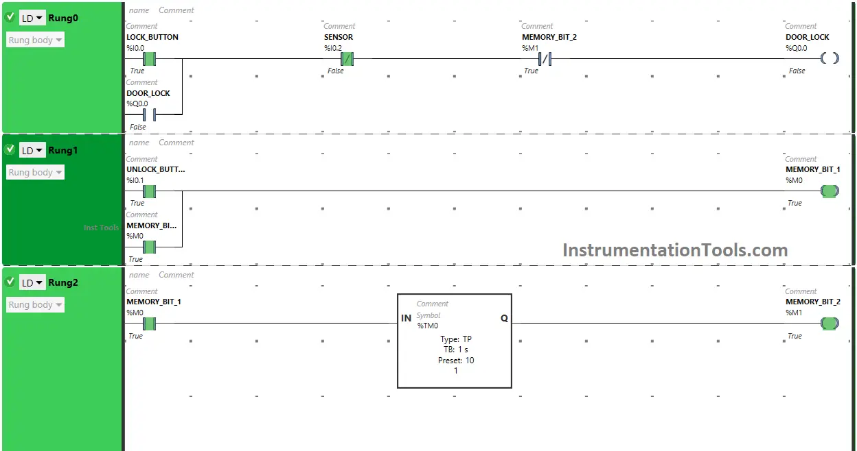
When Memory Bit 1 (M0) turns ON in Rung1, Normally Open Contact used for Memory Bit 1 (M0) in Rung2 will be in True State and will pass the signal to turn ON Memory Bit 2 (M1) but only for 10 seconds as Timer Function Block type TP is used to turn ON the Memory Bit 2 (M1) for Limited time. The time is set to 10 seconds.
After 10 seconds, Memory Bit 2 (M1) will turn OFF. When Memory Bit 2 (M1) turns ON in Rung2, Normally Closed Contact used for Memory bit 2 (M1) will be in True State and does not allow signal to pass through it.
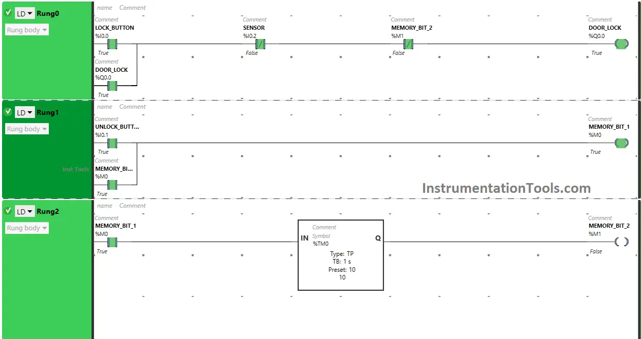
Then, the Output Door Lock (Q0.0) will turn OFF (Doors will Unlock). In Rung2, when Timer Function Block type TP reaches its set time i.e. 10 seconds, Memory Bit 2 (M1) will turn OFF in both Rung2 and Rung0.
When Memory Bit 2 (M1) turns OFF in Rung0 i.e. when Memory Bit 2 (M1) turn OFF in Rung2, Normally Closed Contact used Memory Bit 2 (M1) in Rung0 will be in False state and allow the signal to pass through it and the output Door Lock (Q0.0) will turn ON (Doors will Lock).
When Sensor detects someone at the Door
In Rung0, When sensor (I0.2) gets activated (Sensor detects someone at Door), Normally Closed Contact used for Sensor (I0.2) will be in True state and signal will not pass through it. Then, the output Door Lock (Q0.0) will remain ON till the sensor deactivates (Doors will remains unlocked).
If you liked this article, please subscribe to our YouTube Channel for PLC and SCADA video tutorials.
You can also follow us on Facebook and Twitter to receive daily updates.
Read Next:
- Scaling for Analog Input in RSLogix 500
- InTouch Scada and Allen Bradley PLC
- Upload Option Disabled in Siemens PLC
- Wincc and Tia Portal Communication
- How to Password Protect Siemens HMI?