Inst ToolsInst ToolsInst Tools
  • Courses
  • Automation
    • PLC
    • Control System
    • Safety System
    • Communication
    • Fire & Gas System
  • Instrumentation
    • Design
    • Pressure
    • Temperature
    • Flow
    • Level
    • Vibration
    • Analyzer
    • Control Valve
    • Switch
    • Calibration
    • Erection & Commissioning
  • Interview
    • Instrumentation
    • Electrical
    • Electronics
    • Practical
  • Q&A
    • Instrumentation
    • Control System
    • Electrical
    • Electronics
    • Analog Electronics
    • Digital Electronics
    • Power Electronics
    • Microprocessor
Search
  • Books
  • Software
  • Projects
  • Process
  • Tools
  • Basics
  • Formula
  • Power Plant
  • Root Cause Analysis
  • Electrical Basics
  • Animation
  • Standards
  • 4-20 mA Course
  • Siemens PLC Course
Reading: PLC Program with 2 Toggle Switches and 4 Motors
Share
Notification Show More
Font ResizerAa
Inst ToolsInst Tools
Font ResizerAa
  • Courses
  • Design
  • PLC
  • Interview
  • Control System
Search
  • Courses
  • Automation
    • PLC
    • Control System
    • Safety System
    • Communication
    • Fire & Gas System
  • Instrumentation
    • Design
    • Pressure
    • Temperature
    • Flow
    • Level
    • Vibration
    • Analyzer
    • Control Valve
    • Switch
    • Calibration
    • Erection & Commissioning
  • Interview
    • Instrumentation
    • Electrical
    • Electronics
    • Practical
  • Q&A
    • Instrumentation
    • Control System
    • Electrical
    • Electronics
    • Analog Electronics
    • Digital Electronics
    • Power Electronics
    • Microprocessor
Follow US
All rights reserved. Reproduction in whole or in part without written permission is prohibited.
Inst Tools > Blog > PLC Tutorials > PLC Program with 2 Toggle Switches and 4 Motors

PLC Program with 2 Toggle Switches and 4 Motors

This article will teach you the PLC program with 2 toggle switches and 4 motors logic diagrams.

Last updated: March 22, 2024 7:38 am
Editorial Staff
PLC Tutorials
No Comments
Share
4 Min Read
SHARE

This article will teach you the PLC Program with 2 Toggle Switches and 4 Motors logic diagrams.

Contents
PLC Program with 2 Toggle SwitchesSchneider Electric PLC ExampleInput DetailsOutput Details2 Toggle Switches and 4 Motors LogicLogic Diagram ExplanationPLC Logic Result

Note: The logic diagram example is for students and engineering graduates to learn the PLC basics.

PLC Program with 2 Toggle Switches

Problem Statement

Design a PLC ladder logic for the following application.

We are using two toggle switches to control four motors.

If Switch 1 is ON, then Motor I and Motor II will be ON.

If Switch 1 is OFF, then Motor I will be OFF and Motor II will be ON.

If Switch 2 is ON, then Motor III and Motor IV will be ON.

If Switch 2 is OFF, then Motor III will be OFF and Motor I will be ON.

Schneider Electric PLC Example

Watch this PLC video to learn the programming example.

Simple PLC Example - Schneider Electric PLC Programming

Input Details

Digital Inputs:

This program’s required digital inputs are mentioned below.

Switch 1: I0.0

Switch 2: I0.1

Output Details

Digital Outputs:

This program’s required digital outputs are mentioned below.

Motor 1: Q0.0

Motor 2: Q0.1

Motor 3: Q0.2

Motor 4: Q0.3

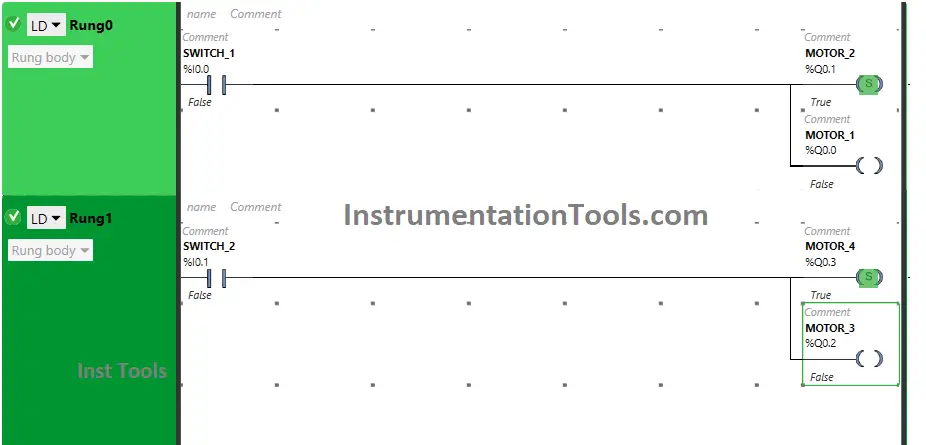
2 Toggle Switches and 4 Motors Logic
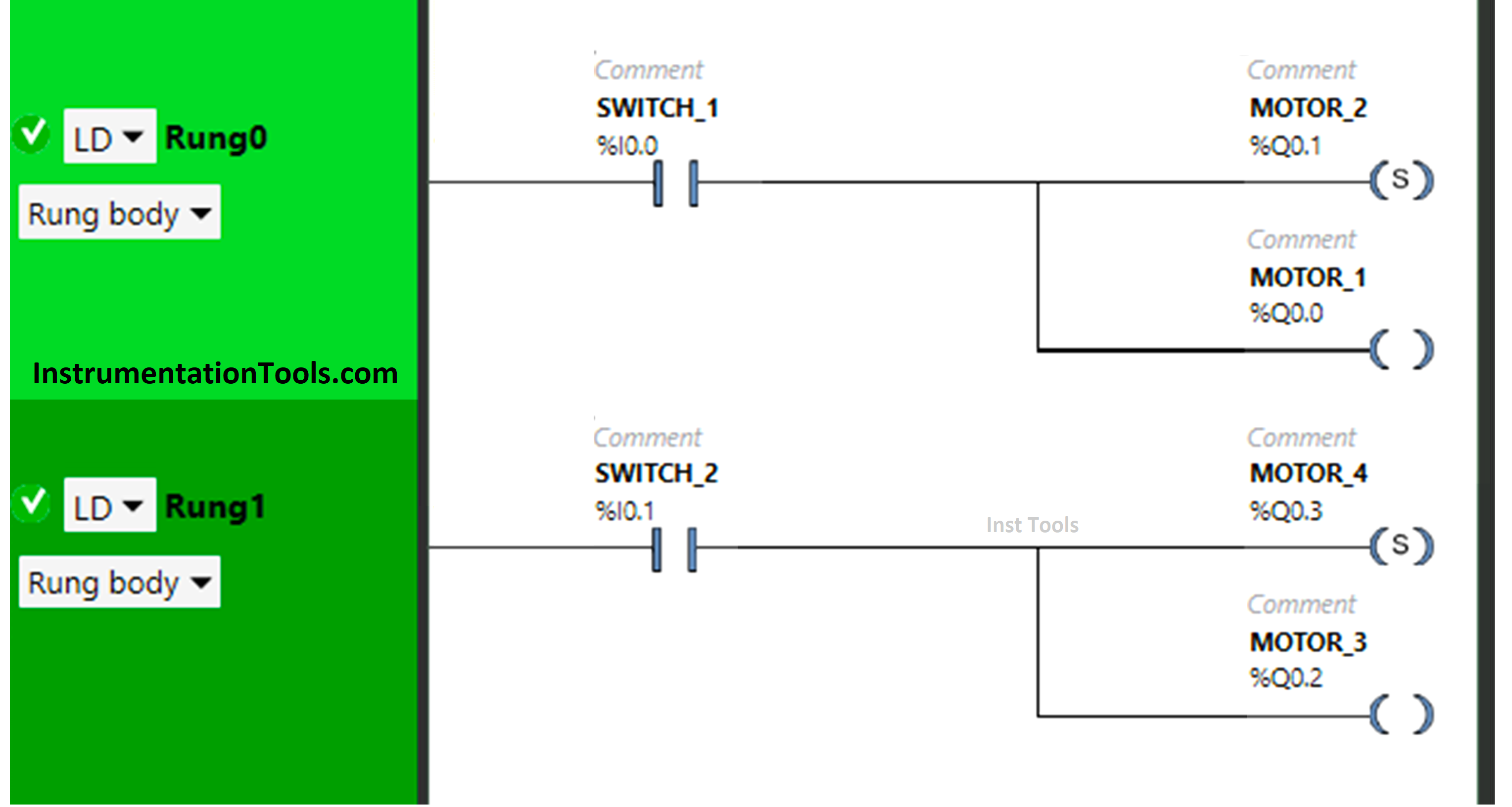
PLC Program with 2 Toggle Switches and 4 Motors

Logic Diagram Explanation

We used EcoStruxure Machine Expert Basic PLC software for this example logic.

In the above program, we have used Normally Open Contact for Switch 1 (I0.0) and Switch 2 (I0.1).

We have used a Set Coil for Motor 2 (Q0.1), Motor 4 (Q0.3), and a normal Coil for Motor 1 (Q0.0), and Motor 3 (Q0.2).

For Motor 1 and Motor 2 to be ON, switch 1 should be ON

When Switch 1 is turned OFF, Motor 1 will turn OFF but Motor 2 will remain ON as we have used Set Coil for it.

Turning ON Switch 2 will turn ON Motor 3 and Motor 4.

Motor 3 will turn OFF when Switch 2 is turned OFF but Motor 4 for which the Set coil is used remains ON.

PLC Logic Result

Now we will see the PLC logic result with different input scenarios.

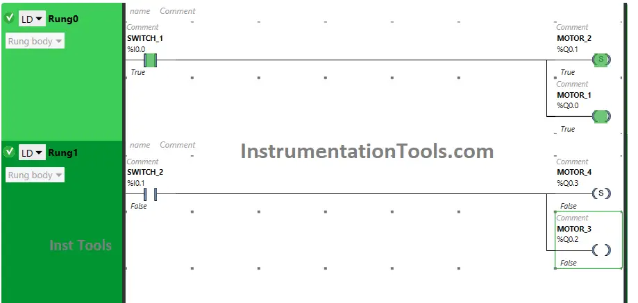
When Switch 1 is ON
program to switch on and off the motor

The signal flows through switch 1 as it is in true state, both Motor 1 and Motor 2 will turn ON.

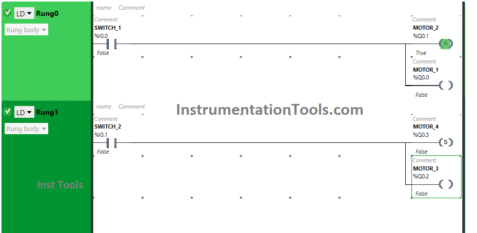
When Switch 1 is OFF
Toggle Switch in PLC Ladder Logic

When switch 1 is turned OFF, Motor 1 will turn OFF and Motor 2 still remains ON as SET coil is used for Motor 2.

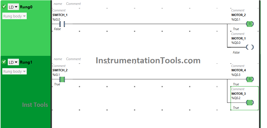
When Switch 2 is ON
How to Toggle a Bit in Ladder Logic

Motor 3 and Motor 4 will turn ON when switch 2 is turned ON. The input Switch 2 is used as Normally open Contact, in the true state, which will allow the signal to pass through it.

When Switch 2 is OFF
PLC Toggle Logic

After turning OFF switch 2, Motor 3 will turn OFF and Motor 4 will remain ON in which SET coil is used.

If you liked this article, please subscribe to our YouTube Channel for PLC and SCADA video tutorials.

You can also follow us on Facebook and Twitter to receive daily updates.

Read Next:

  • Tags in Siemens Scada and PLC
  • How to Get a PLC Programmer Job?
  • Add Unspecified CPU in Tia Portal
  • PLC Based Product Sorting Machine
  • Password Protect HMI in Siemens TIA Portal?
Don't Miss Our Updates
Be the first to get exclusive content straight to your email.
We promise not to spam you. You can unsubscribe at any time.
Invalid email address
You've successfully subscribed !

Continue Reading

SCADA Multiple Choice Questions
PLC Application for Stamping Operation – Example Programming
PLC Programmer Salary and Future Career Scope
Function Block (FB) for Motor Control Logic
Difference Between FC and FB in Tia Portal
PLC Program for Password Management using Structured Text
Share This Article
Facebook Whatsapp Whatsapp LinkedIn Copy Link
Share
Leave a Comment

Leave a Reply Cancel reply

Your email address will not be published. Required fields are marked *

Stay Connected

128.3kFollowersLike
69.1kFollowersFollow
208kSubscribersSubscribe
38kFollowersFollow

Categories

Explore More

What is Thin Client in SCADA? – Purpose, Advantages
What is Recipe Management in SCADA?
Things to Take Care of When Designing SCADA System
PLC vs PAC – Understanding the Key Differences and Similarities
Up Down Counter Instruction in PLC
Automatic Car Washing using PLC
Remote Factory Acceptance Test
Data Types in PLC – Bit, Byte, Integer, Real, String

Keep Learning

PLC datasheet

How to Read the PLC Datasheet? – Important Notes About PLC

Types of Script in Intouch Scada

Types of Script in Intouch Scada

Comparison of Control Loops - Open, Closed, Cascade, Feedforward, Ratio

Comparison of Control Loops – Open, Closed, Cascade, Feedforward, Ratio

Convert Raw Counts to Engineering Units

Raw Counts to Engineering Units : Conversion Formula

Readings Mismatch between Field & Control Room

Readings Mismatch between Field & Control Room ? Why

PLC Program for Automatic Mixing Controlling in a Tank

PLC Program for Automatic Mixing Control in a Tank

Function Block Diagram - Studio 5000 Logix Designer

Define the Order of Execution in Functional Block Diagram of Studio 5000

Problem on PLC, HMI, VFD, and Motor Circuit

Problem on PLC, HMI, VFD, and Motor Circuit

Learn More

Use of Regions in SCL Language

Use of Regions in SCL Language

Types of Tripping Protection in MCCB

Types of Tripping Protection in MCCB

Generator Action in a Motor

Generator Action in a Motor

DTS sensors

Distributed Temperature Sensors (DTS) in Power Lines

Why counter-current heat exchangers are better than co-currents?

Why Counter-current Heat Exchangers are better than Co-current?

Advantages and Applications of zigzag transformer

Why 4-20mA Standard is so popular

Why 4-20 mA Standard is so popular ?

Float Operated Level Switches

Float Level Switch Working Principle

Follow US
All rights reserved. Reproduction in whole or in part without written permission is prohibited.
Welcome Back!

Sign in to your account

Username or Email Address
Password

Lost your password?