Inst ToolsInst ToolsInst Tools
  • Courses
  • Automation
    • PLC
    • Control System
    • Safety System
    • Communication
    • Fire & Gas System
  • Instrumentation
    • Design
    • Pressure
    • Temperature
    • Flow
    • Level
    • Vibration
    • Analyzer
    • Control Valve
    • Switch
    • Calibration
    • Erection & Commissioning
  • Interview
    • Instrumentation
    • Electrical
    • Electronics
    • Practical
  • Q&A
    • Instrumentation
    • Control System
    • Electrical
    • Electronics
    • Analog Electronics
    • Digital Electronics
    • Power Electronics
    • Microprocessor
  • Request
Search
  • Books
  • Software
  • Projects
  • Process
  • Tools
  • Basics
  • Formula
  • Power Plant
  • Root Cause Analysis
  • Electrical Basics
  • Animation
  • Standards
  • 4-20 mA Course
  • Siemens PLC Course
Reading: CANOpen Network Topology
Share
Font ResizerAa
Inst ToolsInst Tools
Font ResizerAa
  • Courses
  • Design
  • PLC
  • Interview
  • Control System
Search
  • Courses
  • Automation
    • PLC
    • Control System
    • Safety System
    • Communication
    • Fire & Gas System
  • Instrumentation
    • Design
    • Pressure
    • Temperature
    • Flow
    • Level
    • Vibration
    • Analyzer
    • Control Valve
    • Switch
    • Calibration
    • Erection & Commissioning
  • Interview
    • Instrumentation
    • Electrical
    • Electronics
    • Practical
  • Q&A
    • Instrumentation
    • Control System
    • Electrical
    • Electronics
    • Analog Electronics
    • Digital Electronics
    • Power Electronics
    • Microprocessor
  • Request
Follow US
All rights reserved. Reproduction in whole or in part without written permission is prohibited.
Inst Tools > Blog > Communication > CANOpen Network Topology

CANOpen Network Topology

CANOpen is a very widely used protocol in industrial automation. In this post, we will learn the various types of CAN Open network topologies.

Last updated: August 1, 2023 10:43 am
Viral Nagda
Communication
No Comments
Share
5 Min Read
SHARE

CANOpen is a very widely used protocol in industrial automation. CANOpen is used in many applications where there are a number of devices requiring to share data with PLC or other controllers. Out of the many protocols used like Ethernet, Modbus, Profinet, Profibus, etc.

Contents
The General Architecture of CANOpen NetworkTypes of CanOpen Network TopologiesBasic TopologyTopology with RepeaterBridge Topology

CAN Open is one which comes between lower-end protocol and higher-end protocol. When an automation engineer works in CAN Open protocol, it is necessary that he has knowledge of various types of network topologies used in it.

In this post, we will learn the various types of CAN Open network topologies.

The General Architecture of CANOpen Network

Refer to the below image for the first understanding of the basic architecture of CAN Open architecture. A CAN Open connection consists of three wires: CAN_High, CAN_Low, and Can_Ground. The one thing that distinguishes this protocol is the requirement for a terminating resistor.

The General Architecture of CANOpen Network

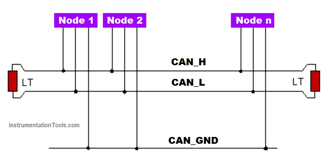
Basically, it needs to understand where it started (Node 1 here in the figure) and where it is ending (Node N here in the figure). So, a resistor is required at both ends as shown in the figure by LT. Without it, the nodes will not communicate with each other. It generally uses twisted pair cables to transmit differential signals.

The resistor value is required at 120 ohms. A separate ground signal is used as a common reference for the CAN-open nodes. One thing must be noted that both the high and low signals must not be shorted with each other. Basically, any of the three connections must not be shorted with each other.

Types of CanOpen Network Topologies

There are three main types of topologies in CANopen communication.

  • Basic Topology
  • Topology with Repeater
  • Bridge Topology

Basic Topology

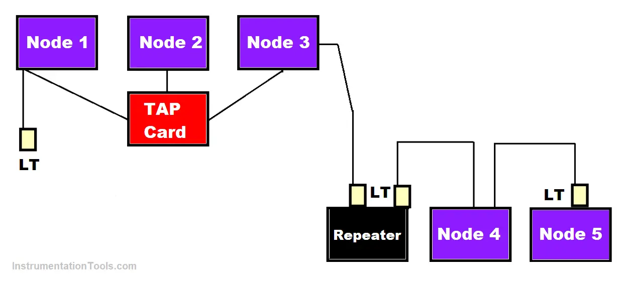
Refer to the below image for understanding the basic topology of CAN Open communication. As seen before, a line termination resistor is used to terminate the connection. In addition to this, a CAN Tap card is also used.

Types of Can Open network topologies

A CAN Tap card forms a partial star topology. This card allows the user to connect all nodes in an interface manner. It nullifies the need to join the nodes by open wires because this card has plug-type ports where you can directly connect the CAN open cable coming from various nodes.

The basic topology also simplifies the system as open and loose wires are always a bad practice to follow in electrical engineering. In order to minimize reflections, keep drop cables as short as possible. The maximum length of drop cables depends on the transmission speed.

Topology with Repeater

The second type comes as repeater topology. The repeater is used as a booster to enable the signals for travelling longer distances. When the distance is longer and the need arises to communicate devices, then a repeater is required in between to amplify the signals.

CAN OPEN Topology with Repeater

Due to the repeater, you can easily connect 64 nodes. Also, it provides isolation between groups. So, if one group of nodes fails, then the second group will remain as it is. Also, amplifying here means it simply forwards the signals.

Bridge Topology

The Bridge topology is the same as the repeater topology, but the difference is that in place of the repeater, a bridge comes into the picture. A CAN-open overall network can be separated into more or less independent sub-networks via a CAN bridge.

A bridge provides individual arbitration for each sub-network. Due to this, the main advantage is that each sub-network can be handled separately. A repeater just forwards the signals, but the bridge can create loops of nodes.

Also, each sub-network can have its own transmission speed. It is based on the store- and forward principle, i.e. CAN messages are received by a sub-network and are then forwarded to another sub-network. So, a bridge network allows network size to be increased to a large extent.

In this way, we saw the various network topologies used in Can Open.

Don't Miss Our Updates
Be the first to get exclusive content straight to your email.
We promise not to spam you. You can unsubscribe at any time.
Invalid email address
You've successfully subscribed !

Continue Reading

Fiber Optic Cable Connectors, Routing, and Safety
Advantages and Disadvantages of Network Topologies
H1 FF Device Configuration and Commissioning
Fieldbus Control
Top 100 Networking Interview Questions & Answers
Modbus : History, Structure, Modes, Addressing, Functions
Share This Article
Facebook Whatsapp Whatsapp LinkedIn Copy Link
Share
Leave a Comment

Leave a Reply Cancel reply

Your email address will not be published. Required fields are marked *

Stay Connected

128.3kFollowersLike
69.1kFollowersFollow
210kSubscribersSubscribe
38kFollowersFollow

Categories

Explore More

Profibus Listener
Network Switch Requirement in SCADA and DCS Architecture
Difference between HART and Foundation Fieldbus
Difference Between Cyclic and Acyclic Communication
What is a Network ?
What is Foundation Fieldbus (FF) ?
Foundation Fieldbus Tutorials
Difference between TCP/IP Model and OSI Model

Keep Learning

WirelessHART Principle

Wireless HART Communication Protocol Overview

Introduction to Fieldbus Function Blocks

Surge Protection for the Fieldbus System

Industrial Automation Protocols

Industrial Automation Protocols

Fieldbus coupling devices

Fieldbus Coupling Devices

Fiber Optic Cable Construction

Fiber Optic Cable Construction

Foundation Fieldbus Segment Topology

Foundation Fieldbus (FF) Segment Topology

Fieldbus Signal Status

FF Signal Status

Learn More

Relationship between Temperature Scales

Relationship between Temperature Scales

Solenoid Valve Failure in Plant Start-Up

Solenoid Valve Failure in Plant Start-Up: Identifying the Root Cause

Types of Pressure

Types of Pressure – Instrument Questions and Answers

Active Barrier

What is a Active Barrier ?

Functional Testing of Control Valve Positioners

Functional Testing of Control Valve Positioners

Best Engineering Mobile Apps

Best Engineering Mobile Apps on Google Play & App Store

What is Transformer Bushing

What is Transformer Bushing? Working Principle

Design Logic Diagrams with Standard Formats for Process Control

Design Logic Diagrams with Standard Formats for Process Control

Menu

  • About
  • Privacy Policy
  • Copyright

Quick Links

  • Learn PLC
  • Helping Hand
  • Part Time Job

YouTube Subscribe

Follow US
All rights reserved. Reproduction in whole or in part without written permission is prohibited.
Welcome Back!

Sign in to your account

Username or Email Address
Password

Lost your password?