Ethernet IP is one of the most advanced and generally used communication protocols in Industrial automation applications. Due to its robust nature and wide range of features, this protocol is a very stable and efficient solution for communication. Many times, engineers get stuck when they troubleshoot any issue in this communication. They can work on basic levels, but when they need some advanced troubleshooting, they face issues with that. In this post, we will see advanced diagnostics in the Ethernet IP communication protocol.
Basic troubleshooting methods for Ethernet IP communication
Before going to advanced levels, let us first revise some basic steps that can be followed by engineers, so that they may help to solve the issue earlier.
- The very first basic step is to check the LEDs on the module or device to be communicated with. If it is off, then either the module has not been configured, or the link is broken, or there is some issue with the communication port. So, check the program settings, then inspect for cable continuity, and if all is fine, then the possibility of port failure can occur (but keep this possibility of port failure in the last step of troubleshooting, all steps which we will discuss next).
- If your IP address conflicts with some other IP address set elsewhere, then communication will not happen. So scan the whole network for IP addresses through some tool like Advanced IP Scanner or Wireshark, and find out duplicate IP addresses associated with a MAC address.
- If the speed of the module is set at 100 Mbps – full duplex, and the Ethernet switch used is 100 Mbps – half duplex, then data packets will be lost, timeouts will happen, and the connection will break. So, check the hardware speed of all the devices to ensure that they are on the same page.
- In PLC’s, if your PLC IP address is 192.168.1.x and your laptop IP address is 192.168.0.x, then the laptop will not be able to ping the PLC. So, be it any device, keep your laptop IP in the same network as the automation network, which can then only help you to connect to these devices and troubleshoot.
Let us now move on to advanced steps. As Ethernet IP is a product of Rockwell Automation, we can use two cases – either between Rockwell products to Rockwell products, or a third-party product using an EDS (electronic datasheet) file addition. Let us see the steps below:
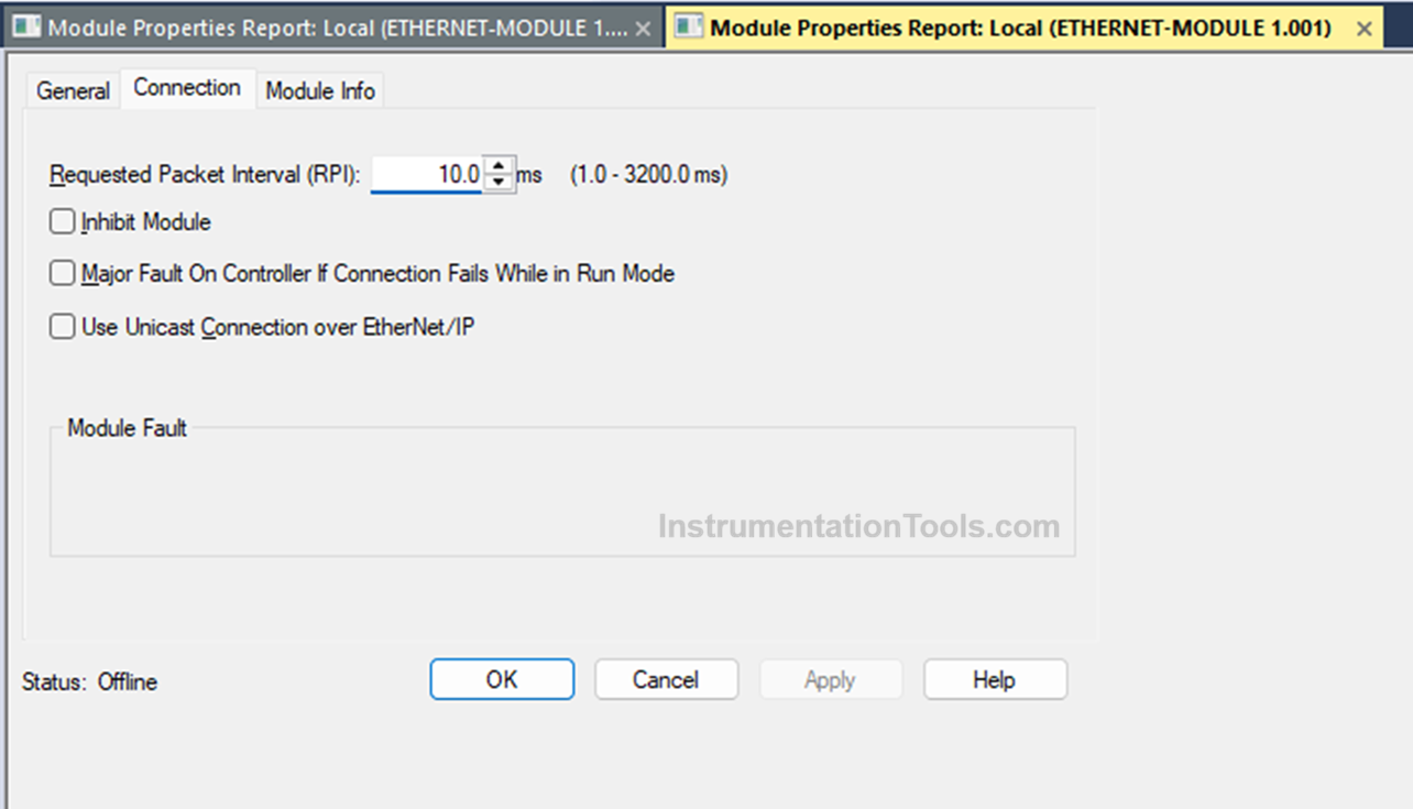
In any case, first check the value of RPI (in milliseconds) or request packet interval. It is basically the speed of data communication. The default value in Rockwell is 10 milliseconds. If you have too many devices on the network, and you have kept a low value for fast communication, then data is communicated too quickly in bulk, which increases network bandwidth and causes the network to overload and break down.
Connection timeout happens frequently in this case, as packets get dropped. A high value of RPI is not as dangerous as compared to a low RPI, which we discussed, but it makes the process very slow to operate. So, always calculate the network load (for that, calculate the total number of devices on the network, the data they will communicate, and the speed set in the configuration) and set the appropriate value.
Then, you have to check the unicast/multicast setting in the Ethernet-IP communication configuration. Unicast means one to one (meaning a device with unicast selected can send data to PLC only), and multicast means one to many (meaning a device with unicast deselected can send data to any device that joins the network). Multicast consumes more bandwidth and requires managed switches due to any device joining the network for data.
Simply, in any software configuration, if a device is the owner (like PLC in Studio 5000) and unicast is selected in another server device (like AENT in Studio 5000, then that device will communicate with PLC only. So, when you are trying to get data to SCADA directly from that device with unicast, the data will not be communicated to SCADA.
When choosing multicast, care must be taken to use IGMP (Internet Group Management Protocol), as IGMP controls who should receive multicast packets and who should not, failing which the multicast behaves like broadcast and floods the network, causing data loss.
For simple non-critical communication, forcing multicast is not the recommended option. If two PLCs incorrectly join the same multicast group with the wrong RPI, then data inconsistencies will occur, and timeouts will happen frequently. Refer to the image below for RPI and unicast settings as an example.
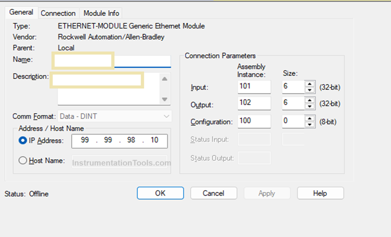
If you add an EDS file for a third-party product, then you need to enter the assembly instance number (the number from which data communication starts) and the size of the instance to be read. If a wrong number is entered in any of the fields, then the communication will not happen.
So, you need to check the data manual and refer to the correct number from which data will be read or written with that device, and what data size it will accept. Also, some EDS files allow for editing of data type selection. Choose the correct data type accordingly. Refer to the image below for an example.
Almost every Ethernet/IP device exposes CIP objects. They are identity (vendor, device type, status), assembly (real-time I/O data), TCP/IP (IP config, domain, DNS), etc. The software configuring Ethernet/IP devices can allow reading of this data for status and troubleshooting. This helps in quick guidance for the engineers, without any need to manually check every step. With this CIP layer, you can thus check the connection object status, identity object (device reset reason if done), and IO connection timeout counters.
If you are using an EDS file for a third-party device, it is always necessary to match the revision number and model number of the device with the ones in the file you get from the internet. If there is a mismatch, then communication will not happen. Many times, it is possible that if you do not get the exact EDS file, then a generic EDS one can work too. But that needs to be tested thoroughly at the factory before commissioning.
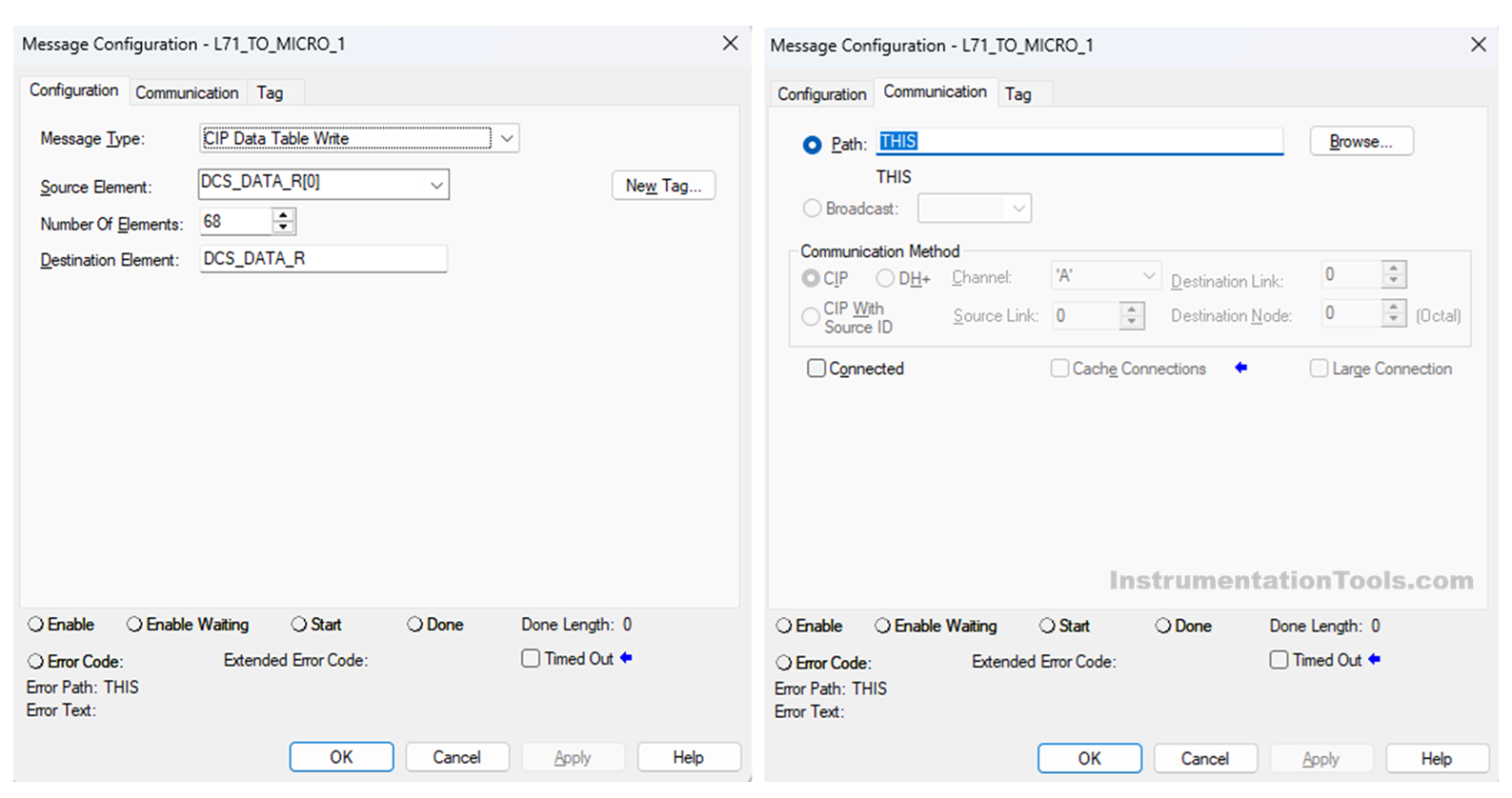
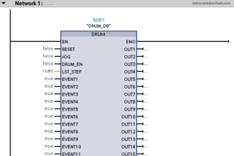
If you are using a message instruction in Studio 5000, then check whether the tags mentioned in the source element and destination element are correct, with the correct number of elements to be communicated. Also, check for the correct message type. At last, check the communication path of the destination device, which is entered in the message instruction. Refer to the image above for more details.