Inst ToolsInst ToolsInst Tools
  • Ask
  • Courses
  • Videos
  • Q & A
    • Interview
      • Instrumentation
      • Electronics
      • Electrical
      • Practical Questions
    • MCQ
      • Instrumentation MCQ
      • Electrical MCQ
      • Electronics MCQ
      • Control Systems MCQ
      • Analog Electronics MCQ
      • Digital Electronics MCQ
      • Power Electronics MCQ
      • Microprocessor MCQ
      • Multiple Choice Questions
  • EE
    • Electronics
      • Electronics Q & A
      • Electronic Basics
      • Electronic Devices & Circuits
      • Electronics Animation
      • Digital Electronics
    • Electrical
      • Electrical Basics
      • Electrical Q & A
      • Power Electronics
      • Electrical Machines
      • Electrical Animation
      • Power Systems
      • Switchgear & Protection
      • Transmission & Distribution
  • Measure
    • Control Valves
    • Calibration
    • Temperature
    • Pressure
    • Flow
    • Level
    • Analyzers
    • Switches
    • Vibration
    • Solenoid Valve
  • Control
    • PLC Tutorials
    • Control Systems
    • Safety Instrumented System (SIS)
    • Communication
    • Fire & Gas System
  • More
    • Design
    • Tools
    • Animation
    • Basics
    • Formulas
    • Standards
    • TextBooks
    • Common
    • Software
    • Excel Tools
    • Erection & Commissioning
    • Process Fundamentals
    • Videos
    • Books
Search
All rights reserved. Reproduction in whole or in part without written permission is prohibited.
Reading: Zener Diode Voltage Regulators
Share
Notification Show More
Font ResizerAa
Inst ToolsInst Tools
Font ResizerAa
  • Courses
  • PLC Tutorials
  • Control Systems
Search
  • Ask
  • Courses
  • Videos
  • Q & A
    • Interview
    • MCQ
  • EE
    • Electronics
    • Electrical
  • Measure
    • Control Valves
    • Calibration
    • Temperature
    • Pressure
    • Flow
    • Level
    • Analyzers
    • Switches
    • Vibration
    • Solenoid Valve
  • Control
    • PLC Tutorials
    • Control Systems
    • Safety Instrumented System (SIS)
    • Communication
    • Fire & Gas System
  • More
    • Design
    • Tools
    • Animation
    • Basics
    • Formulas
    • Standards
    • TextBooks
    • Common
    • Software
    • Excel Tools
    • Erection & Commissioning
    • Process Fundamentals
    • Videos
    • Books
Follow US
All rights reserved. Reproduction in whole or in part without written permission is prohibited.
Inst Tools > Blog > Electronic Basics > Zener Diode Voltage Regulators

Zener Diode Voltage Regulators

Last updated: December 12, 2018 7:50 am
Editorial Staff
Electronic Basics Instrumentation Design
2 Comments
Share
4 Min Read
SHARE

Zener Diodes can be used to produce a stabilised voltage output with low ripple under varying load current conditions. By passing a small current through the diode from a voltage source, via a suitable current limiting resistor (RS), the zener diode will conduct sufficient current to maintain a voltage drop of Vout.

Zener Diodes are widely used as Shunt Voltage Regulators to regulate voltage across small loads. Zener Diodes have a sharp reverse breakdown voltage and breakdown voltage will be constant for a wide rang of currents. Thus we will connect the zener diode parallel to the load such that the applied voltage will reverse bias it. Thus if the reverse bias voltage across the zener diode exceeds the knee voltage, the voltage across the load will be constant.

Here we are discussing troubleshooting of Zener diode based voltage regulators.

Zener Regulated DC Power Supply

The Below Figure shows a filtered dc power supply that produces a constant 24 V before it is regulated down to 15 V by the zener regulator. The 1N4744A zener diode used. A no-load check of the regulated output voltage shows 15.5 V as indicated in part (a). The typical voltage expected at the zener test current for this particular diode is 15 V.

Zener Regulated DC Power Supply

Zener Power Supply

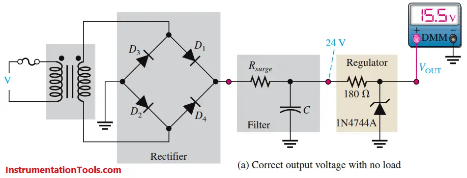
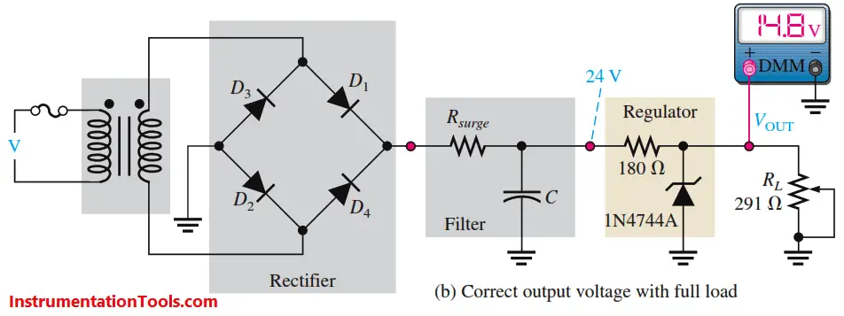
Fig : Zener-regulated power supply test

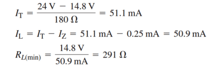
In part (b), a potentiometer is connected to provide a variable load resistance. It is adjusted to a minimum value for a full-load test as determined by the following calculations. The full-load test is at minimum zener current (IZK). The meter reading of 14.8 V indicates approximately the expected output voltage of 15.0 V.

Zener Power Supply Equation

Case 1:

Zener Diode Open If the zener diode fails open, the power supply test gives the approximate results indicated in Figure. In the no-load check shown in part (a), the output voltage is 24 V because there is no voltage dropped between the filtered output of the power supply and the output terminal. This definitely indicates an open between the output terminal and ground. In the full-load check, the voltage of 14.8 V results from the voltage-divider action of the 180 ohms series resistor and the 291 ohms load.In this case, the result is too close to the normal reading to be a reliable fault indication but the no-load check will verify the problem. Also, if RL is varied, VOUT will vary if the zener diode is open.

Open zener diode with no load

Zener Diode Regulator

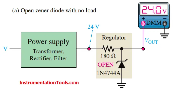
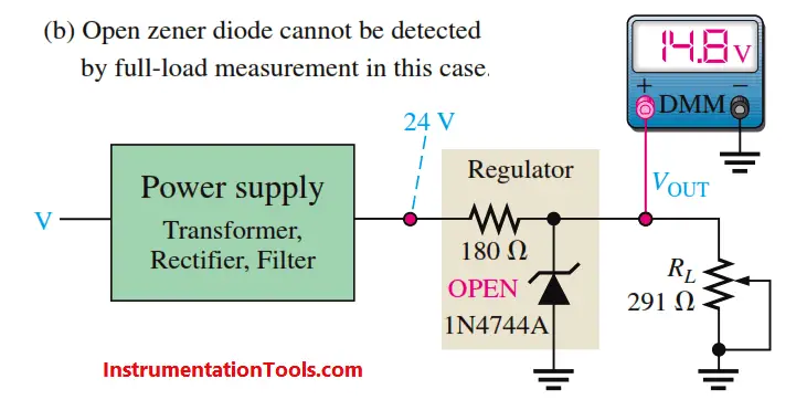
Fig : Indications of an open zener

Case 2:

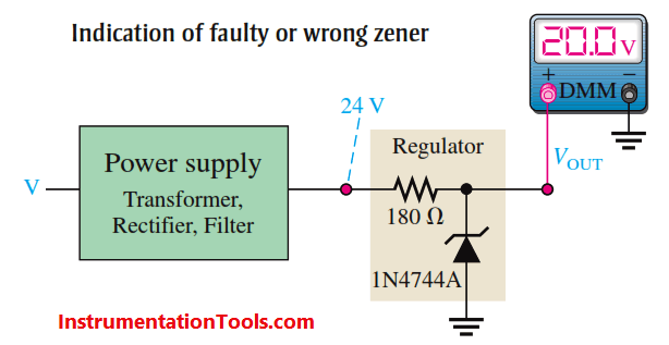
Incorrect Zener Voltage As indicated in Below Figure, a no-load check that results in an output voltage greater than the maximum zener voltage but less than the power supply output voltage indicates that the zener has failed such that its internal impedance is more than it should be. The 20 V output in this case is 4.5 V higher than the expected value of 15.5 V. That additional voltage indicates the zener is faulty or the wrong type has been installed. A 0 V output, of course, indicates that there is a short.

Indication of faulty or wrong zener

Don't Miss Our Updates
Be the first to get exclusive content straight to your email.
We promise not to spam you. You can unsubscribe at any time.
Invalid email address
You've successfully subscribed !
Relay Loop Back Circuit
Design Document for Project Systems Architecture
Major issues for Sensors Selection
100 Electronics and Electrical Projects for Engineering Students
Difference between Intrinsic Safe and Non-Intrinsic Safe Cables
Share This Article
Facebook Whatsapp Whatsapp LinkedIn Copy Link
Share
2 Comments
  • pasha says:
    August 24, 2016 at 4:13 pm

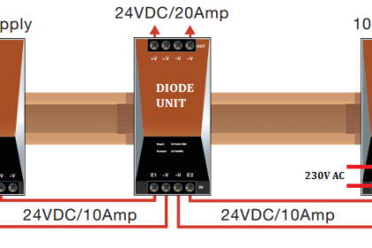
    I want to know about ac and DC supply to diode

    Reply
  • George Ibraheem Yokhana says:
    April 30, 2018 at 11:59 am

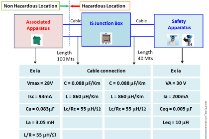
    As i know Zener Diode used as a voltage regulator in what is so called the Intrinsically safe system ,especially when we have field instrument installed in hazard Area ,So Zener will play the role of fuse protection i.e. will keep the voltage within safe limits below 24VDC .

    And we know all transmitters are provided with electronic component especially Capacitors ,for this each loop of two wire system has its own intrinsic safety Zener Barrier .this part of power regulation to ensure that the regulated voltage will be feed to all field instruments with safe limits is the most important one which to be consider in HAZARD Area application and how we can protect our equipment from voltage overshoot and to avoid unexpected measures due to this phenomena ,in addition to how we can protect our signals from other cases like using cable glands and explosion proof junction boxes etc according to international standards been applied in the field of Hazard Area

    Reply

Leave a Reply Cancel reply

Your email address will not be published. Required fields are marked *

Stay Connected

128.3kFollowersLike
69.1kFollowersFollow
208kSubscribersSubscribe
38kFollowersFollow

Categories

Recent Comments

  • Kamli on Top Free PLC Software
  • Guifty Shimica on Top Non-PLC Certification Courses for Automation Professionals
  • Guifty Shimica on Top Non-PLC Certification Courses for Automation Professionals
  • MIHARITSOA Aina Sitraka on Top Non-PLC Certification Courses for Automation Professionals

Related Articles

Instrumentation Project Documents

List of Instrumentation Project Engineering Documents

Pressure Regulators vs Pressure Control Valves

Pressure Control Valves vs Pressure Regulators

Ferrule Example

Ferrules and Cross Ferruling

Industrial Process Plant Project Execution Cycle

Detail Design Engineering Competency Aspects

Instrument Loop Diagram

How-to Create Instrument Loop Diagram (ILD)?

Level Transmitter Design

Level Transmitter and Level Gauge Design Tips

Control System Vendor Internal Test Procedures

Vendor View of Supplying Industrial Process Control & Safety Systems

What to Choose RTD or Thermocouple ?

More Articles

Cable Trays

Types of Cable Trays – Purpose, Advantages, Disadvantages

Bipolar Junction Transistors Questions & Answers

Bipolar Junction Transistors Questions & Answers

Technologies for Oxygen Gas Measurement

How to Calibrate Oxygen Analyzer? – O2 Sensor Testing Procedure

Filled-bulb Temperature Measurement

Filled-bulb Temperature Sensors

Digital Electronics Multiple Choice Questions

Flip Flops Objective Questions – Part 2

Best Engineering Mobile Apps

Best Engineering Mobile Apps on Google Play & App Store

Compressor Did Not Trip

RCA – Compressor Did Not Trip on Suction Pressure Low Low

Difference Between Open Circuit and Close Circuit

Difference Between Open Circuit and Close Circuit

Follow US
All rights reserved. Reproduction in whole or in part without written permission is prohibited.
Welcome Back!

Sign in to your account

Username or Email Address
Password

Lost your password?