You will learn the motor feedback fail logic in PLC which initiates an alarm signal if the motor was not started in 5 seconds.
Let us understand the logic written for detecting motor failure and stopping the system.
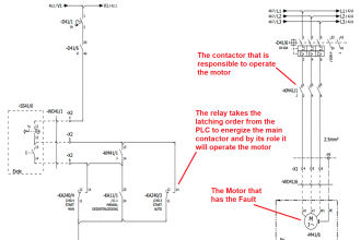
A start pushbutton is used to start the motor. A stop button is used to stop the motor. After pressing the start pushbutton, the motor will be started but due to any other reasons if the motor was not started in 5 seconds then initiate an alarm.
This logic is basically divided into four rungs.
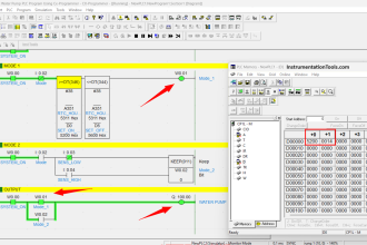
Motor Feedback Fail Logic in PLC
Let us understand the flow of each rung one by one:
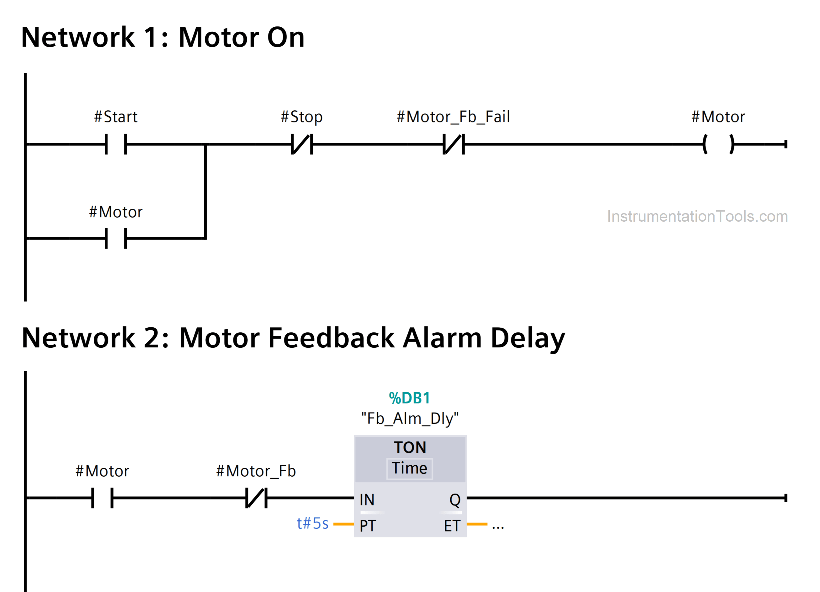
- Start button and stop button are used as PLC inputs. The motor is the digital output. Start button is NO contact and stop button is NC contact. On pressing start button, the motor will start and latch in parallel with start button. This is written in first rung
- In the second rung, we check for motor feedback after motor turns ON. If feedback is not received after 5 seconds, then the alarm timer will turn ON.
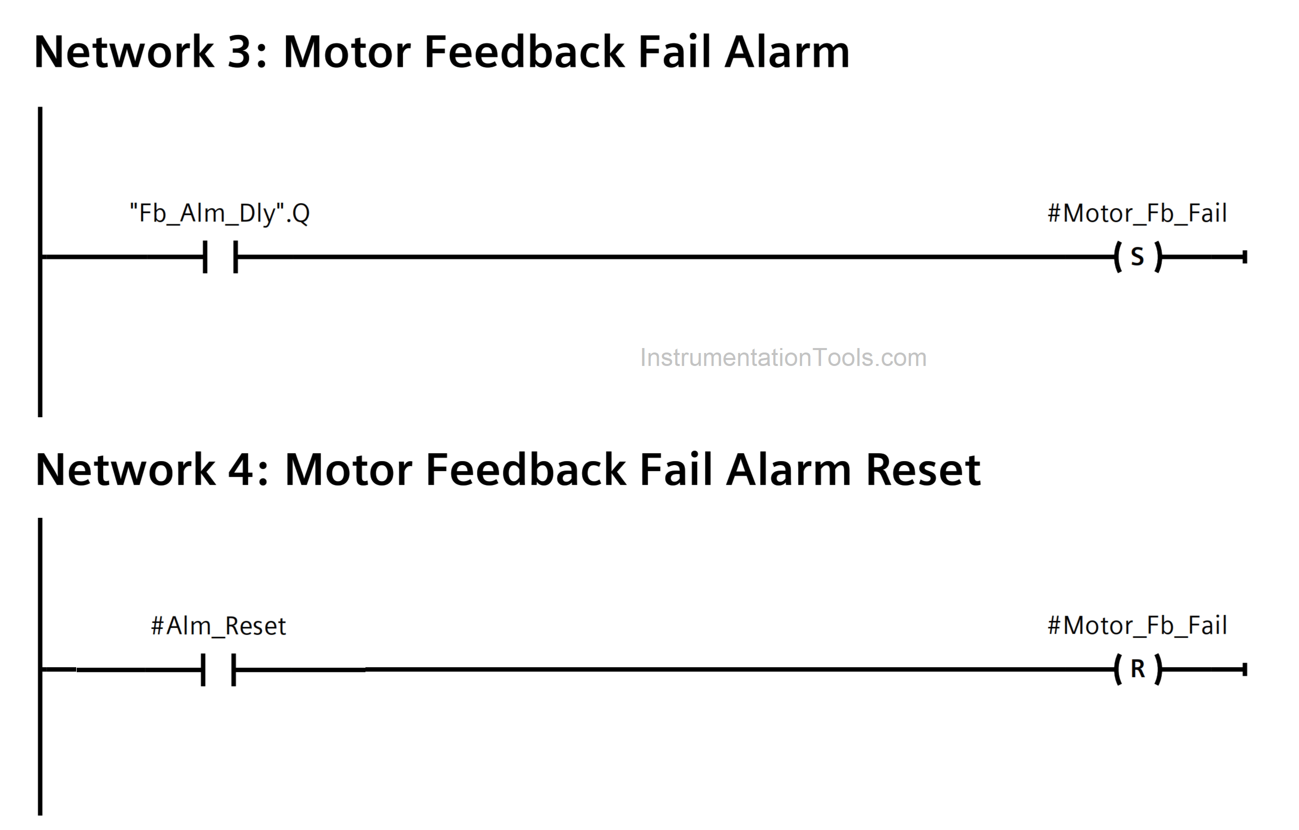
- In the third rung, the alarm timer output turns on the alarm bit and latches it. As soon as this happens, the first rung is cut off due to alarm contact, and the motor turns OFF. Now, the motor will remain OFF as long as the alarm is ON.
- In the fourth rung, the alarm reset input is used to reset the alarm. As soon as the alarm is reset, the motor path will again become open for operation in the first rung. Then, after pressing start button, the cycle repeats.
If you liked this article, then please subscribe to our YouTube Channel for Instrumentation, Electrical, PLC, and SCADA video tutorials.
You can also follow us on Facebook and Twitter to receive daily updates.
Read Next:
- Automation Documents
- Delta PLC & VFD Modbus
- Compare PLC and SCADA
- PLC and DCS System Checks
- DCS System Maintenance


how can the timer work while not getting power supply
Is #Motor_Fb tag in rung 2 a PLC input?
Yes, motor running feedback from substation/mcc.