Inst ToolsInst ToolsInst Tools
  • Courses
  • Automation
    • PLC
    • Control System
    • Safety System
    • Communication
    • Fire & Gas System
  • Instrumentation
    • Design
    • Pressure
    • Temperature
    • Flow
    • Level
    • Vibration
    • Analyzer
    • Control Valve
    • Switch
    • Calibration
    • Erection & Commissioning
  • Interview
    • Instrumentation
    • Electrical
    • Electronics
    • Practical
  • Q&A
    • Instrumentation
    • Control System
    • Electrical
    • Electronics
    • Analog Electronics
    • Digital Electronics
    • Power Electronics
    • Microprocessor
Search
  • Books
  • Software
  • Projects
  • Process
  • Tools
  • Basics
  • Formula
  • Power Plant
  • Root Cause Analysis
  • Electrical Basics
  • Animation
  • Standards
  • 4-20 mA Course
  • Siemens PLC Course
Reading: What is a Solid State Relay? – Working Principle, Types of Control
Share
Notification Show More
Font ResizerAa
Inst ToolsInst Tools
Font ResizerAa
  • Courses
  • Design
  • PLC
  • Interview
  • Control System
Search
  • Courses
  • Automation
    • PLC
    • Control System
    • Safety System
    • Communication
    • Fire & Gas System
  • Instrumentation
    • Design
    • Pressure
    • Temperature
    • Flow
    • Level
    • Vibration
    • Analyzer
    • Control Valve
    • Switch
    • Calibration
    • Erection & Commissioning
  • Interview
    • Instrumentation
    • Electrical
    • Electronics
    • Practical
  • Q&A
    • Instrumentation
    • Control System
    • Electrical
    • Electronics
    • Analog Electronics
    • Digital Electronics
    • Power Electronics
    • Microprocessor
Follow US
All rights reserved. Reproduction in whole or in part without written permission is prohibited.
Inst Tools > Blog > Electrical Basics > What is a Solid State Relay? – Working Principle, Types of Control

What is a Solid State Relay? – Working Principle, Types of Control

In this article, you will learn about what is a solid state relay (SSR), working principle and types of control methods.

Last updated: September 28, 2022 3:44 pm
Viral Nagda
Electrical Basics
No Comments
Share
5 Min Read
SHARE

In this post, we will cover the basic concepts of solid state relay.

Contents
What is a Solid State Relay?Solid State Relay Working PrincipleTypes of Control for Solid State RelaysRandom Turn-On of Solid State RelayZero Crossing of Solid State RelayProportional Control of Solid State Relay

One of the most important components used in an electrical panel is a relay. Mostly, people are familiar with standard electromechanical relays.

But, there is another type of relay which is also used widely for a large variety of loads – mainly heavy and resistive types. This is a solid state relay (SSR). In this post, we will understand the basic concept of a solid state relay.

What is a Solid State Relay?

As the name implies, solid state relay (SSR) works on semiconductors. In contrast to an electromechanical relay which uses mechanical contacts to switch on or off a circuit, there are no mechanical contacts inside the solid state relay.

Switching is done swiftly through semiconductors like triac, transistor, diode, and thyristors. The technique works on either infrared light emitting diodes or LED couplers to operate. Due to the use of semiconductors, the switching is very fast as compared to a standard electromechanical relay.

Also, you can get a wide variety of control voltage from SSR, either fixed or variable, due to the use of semiconductors. The solid state relay is mostly used for resistive and heavy loads like heaters and heat tracings, which require a large amount of load current.

Solid State Relay Working Principle

Refer to the below figure. As discussed before, solid state relay (SSR) does not have moving parts. They consist of semiconductors and electronic parts.

Solid State Relay Working Principle

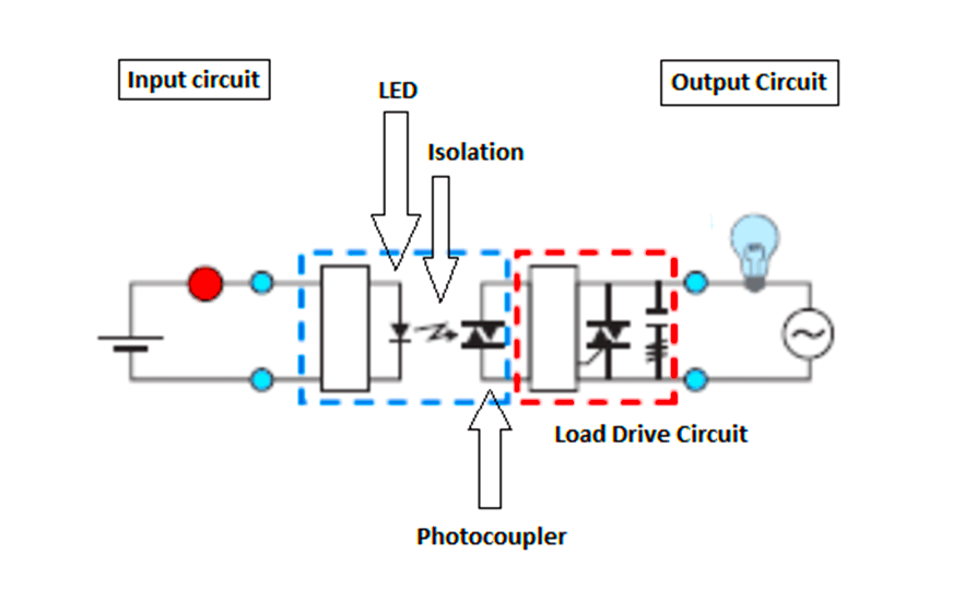
The input circuit consists of a LED which is triggered by the input voltage. Then, there is isolation between input and output circuits.

The output circuit consists of a photo-coupler for capturing the light and converting it into electrical energy for the load drive circuit (consisting of either triac, diodes, transistors, or thyristors).

When the power supply is applied to the input circuit, current flows through LED which emits light from it. The photo-coupler detects it and converts it into an electrical voltage which is then fed to the load drive circuit, for controlling the final output voltage to the load. When the input voltage turns off, the load too turns off.

Due to the use of Opto-coupling technology, the switching is swift, sensitive, and has high insulation levels. The output voltage can be digital or analog, depending upon the input circuit and load drive circuit used.

Types of Control for Solid State Relays

There are three types of control methods available for solid state relays (SSR).

They are as follows

  1. Random Turn-On of Solid State Relay
  2. Zero crossing of Solid State Relay
  3. Proportional Control of Solid State Relay

Random Turn-On of Solid State Relay

When the input voltage is applied as shown in the figure, the output voltage immediately turns on and is applied for the whole AC cycle as long as the input voltage is on.

Random Turn-On of Solid State Relay

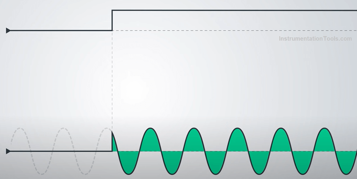
As soon as it turns off, the output voltage also turns off.

Zero Crossing of Solid State Relay

As shown in the figure below, when the input voltage is applied, the output voltage does not immediately turn on; rather it starts the cycle as soon as it touches the next available zero point in the waveform.

Zero Crossing of Solid State Relay

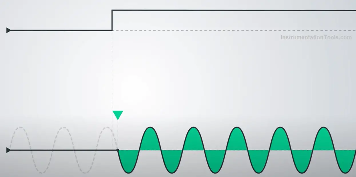
Then, it is applied for the whole AC cycle as long as the input voltage is on. When the input voltage is released, the output voltage does not immediately turn off; rather it stops the cycle as soon as it touches the next available zero point in the waveform.

Proportional Control of Solid State Relay

The earlier two types we discussed were digital output types. As the name implies, proportional control solid state relay provides an analog output.

Proportional Control of Solid State Relay

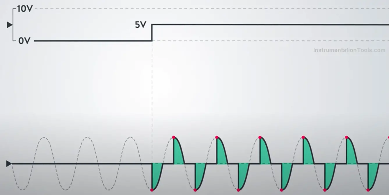
According to the input voltage given, the output voltage will be given accordingly. This type is used for PID control of heaters and other devices, where accurate control of temperature is required.

In this way, we saw the concept of solid state relay, and it is widely used in many types of loads.

If you liked this article, then please subscribe to our YouTube Channel for Instrumentation, Electrical, PLC, and SCADA video tutorials.

You can also follow us on Facebook and Twitter to receive daily updates.

Read Next:

  • Servo Motor Control Drives
  • Industrial Storage Batteries
  • Motor Timer Control Circuit
  • Switched Mode Power Supply
  • Variable Frequency Drive (VFD)
Don't Miss Our Updates
Be the first to get exclusive content straight to your email.
We promise not to spam you. You can unsubscribe at any time.
Invalid email address
You've successfully subscribed !

Continue Reading

Circuit Breaker Making Capacity
What is an Intelligent Motor Control Center? – IMCC
Electric Stress Control in Cables, Joints, and Terminations
What is an HRC Fuse? – Material, Types, Advantages
What is Electrical Slip Ring? Principle, Types, Advantages, Applications
How does Electrical Power Outlet Work?
Share This Article
Facebook Whatsapp Whatsapp LinkedIn Copy Link
Share
Leave a Comment

Leave a Reply Cancel reply

Your email address will not be published. Required fields are marked *

Stay Connected

128.3kFollowersLike
69.1kFollowersFollow
210kSubscribersSubscribe
38kFollowersFollow

Categories

Explore More

Why V/f Ratio is kept Constant in VFD?
Basics of Electricity Rates
Electric Motors Noises – Types, Possible Sources, Reasons
Top 100 Electrical Machines Projects for Electrical Engineers
What is ELCB? Principle, Advantages, Disadvantages, Applications
Motor STAR – DELTA Starter Working Principle
Difference Between NEMA and IEC Motors?
Difference Between Normal Inverter and Solar Inverter

Keep Learning

RDOL starter

What are DOL and RDOL starters? Advantages, Disadvantages

How do AC drives work

How do AC Drives Work? – Variable Frequency Drive (VFD)

Electrical Engineering Documents

Electrical Engineering Documents – Engineers Questions

corroded tank

Cathodic Protection – Sacrificial Anodic and Impressed Current

PLC and MCC Panel Interface Design

PLC Panel and MCC Panel Interface Signals

Offline UPS

UPS Working Principle and Types – Offline and Online UPS Systems

Types of Tripping Protection in MCCB

Types of Tripping Protection in MCCB

Vacuum Circuit Breaker Principle

What is Vacuum Circuit Breaker?

Learn More

Synchronous Motor Is Not Self Starting?

Induction Motor Interview Questions & Answers

Induction Motor Interview Questions & Answers

DC Circuit Node Equations

DC Circuit Analysis Node Equations

Automation in laboratory

Automating Lab Data Reconciliation: Key Steps to Success

Shift Registers and Counters Objective Questions

Shift Registers and Counters Objective Questions

Electromagnetic Noise Interference

What is Electromagnetic Noise Interference?

Electrical Motor Jogging Operation

Electrical Motor Jogging Operation

Library of PlantPAx Process Objects

How to Download PlantPAx Library?

Menu

  • About
  • Privacy Policy
  • Copyright

Quick Links

  • Learn PLC
  • Helping Hand
  • Part Time Job

YouTube Subscribe

Follow US
All rights reserved. Reproduction in whole or in part without written permission is prohibited.
Welcome Back!

Sign in to your account

Username or Email Address
Password

Lost your password?