Inst ToolsInst ToolsInst Tools
  • Courses
  • Automation
    • PLC
    • Control System
    • Safety System
    • Communication
    • Fire & Gas System
  • Instrumentation
    • Design
    • Pressure
    • Temperature
    • Flow
    • Level
    • Vibration
    • Analyzer
    • Control Valve
    • Switch
    • Calibration
    • Erection & Commissioning
  • Interview
    • Instrumentation
    • Electrical
    • Electronics
    • Practical
  • Q&A
    • Instrumentation
    • Control System
    • Electrical
    • Electronics
    • Analog Electronics
    • Digital Electronics
    • Power Electronics
    • Microprocessor
  • Request
Search
  • Books
  • Software
  • Projects
  • Process
  • Tools
  • Basics
  • Formula
  • Power Plant
  • Root Cause Analysis
  • Electrical Basics
  • Animation
  • Standards
  • 4-20 mA Course
  • Siemens PLC Course
Reading: Single Phase versus Three Phase Power
Share
Notification Show More
Font ResizerAa
Inst ToolsInst Tools
Font ResizerAa
  • Courses
  • Design
  • PLC
  • Interview
  • Control System
Search
  • Courses
  • Automation
    • PLC
    • Control System
    • Safety System
    • Communication
    • Fire & Gas System
  • Instrumentation
    • Design
    • Pressure
    • Temperature
    • Flow
    • Level
    • Vibration
    • Analyzer
    • Control Valve
    • Switch
    • Calibration
    • Erection & Commissioning
  • Interview
    • Instrumentation
    • Electrical
    • Electronics
    • Practical
  • Q&A
    • Instrumentation
    • Control System
    • Electrical
    • Electronics
    • Analog Electronics
    • Digital Electronics
    • Power Electronics
    • Microprocessor
  • Request
Follow US
All rights reserved. Reproduction in whole or in part without written permission is prohibited.
Inst Tools > Blog > Electrical Basics > Single Phase versus Three Phase Power

Single Phase versus Three Phase Power

In this article, we will learn the difference between single-phase and three-phase power supply and their comparison.

Last updated: September 28, 2022 4:09 pm
Viral Nagda
Electrical Basics
No Comments
Share
6 Min Read
SHARE

In this post, we will see the difference between single-phase and three-phase power supply.

Contents
Single-Phase Power SupplyThree-Phase Power SupplySingle Phase versus Three Phase Power

Most of us are familiar with AC (Alternating current) power supply. It is used in our day-to-day life for getting electricity.

AC supply means current changes, in both the terms of magnitude and phase direction. It means that it is not always positive; and switches between positive and negative output. It is in total contrast with DC (Direct current) power supply system where the phase does not change and the output is always positive.

In AC power supply, there are two types of systems used – single-phase and three-phase.

Earlier, there used to be the third one too – a dual-phase power supply. But, it has become obsolete now and is not used anymore.

Our normal life revolves around these two power supply systems. In this post, we will understand what are they and what is the difference between them.

Single-Phase Power Supply

This system consists only of two wires – line (phase) and neutral. It must be noted that an AC current flows in phase theory (distribution of load).

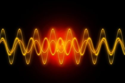
Basically, let us consider a sinusoidal wave.

Single-Phase Power Supply

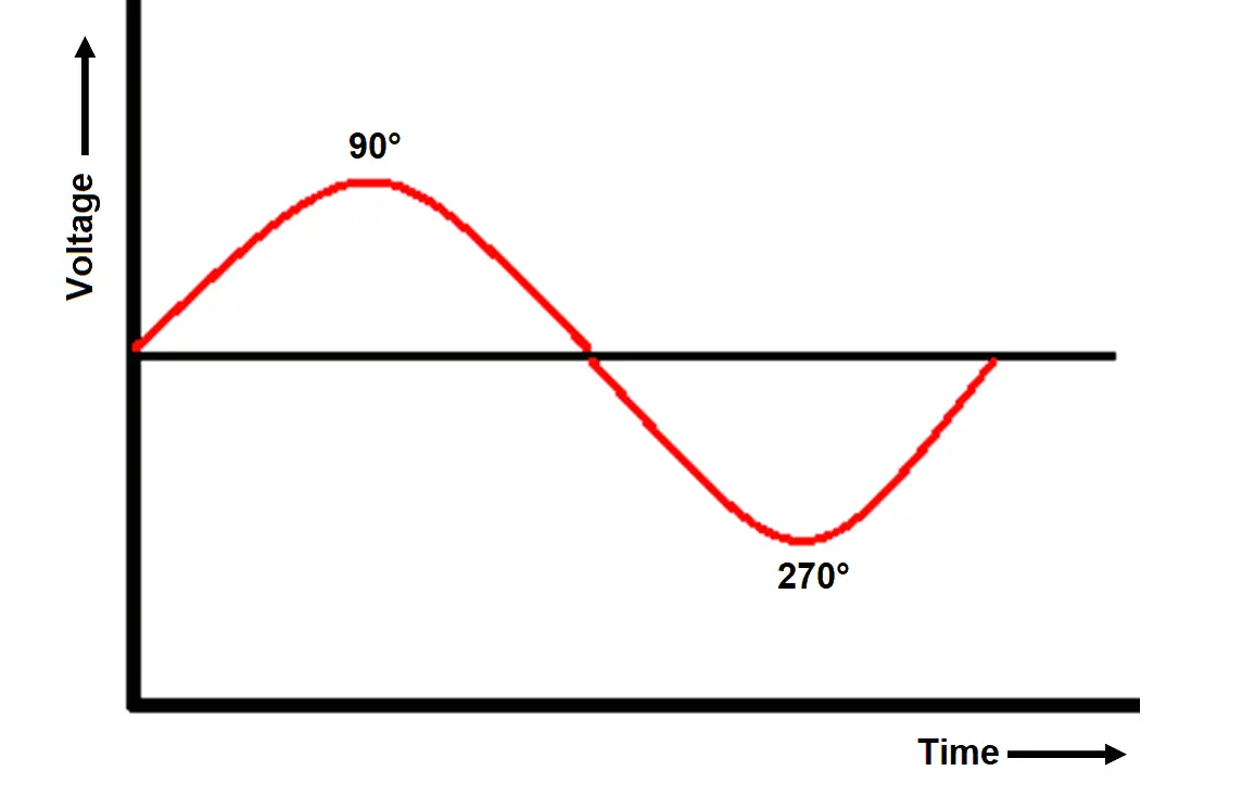
Refer to the above image. As shown, the wave peaks in the positive form at 90 deg. and peaks in the negative form at 270 deg.

The voltage supplied between phase and neutral is 230V. It is found that due to a single waveform and positive cycle is not the whole duration (presence of negative cycle in every interval), constant power is not supplied to the load. This shows that a single-phase system will supply less output power.

Three-Phase Power Supply

This system consists of four wires – 3 wires of the line (phase) and neutral.

Refer to the below image. As shown, the wave peaks in the positive form at every angle. Let us understand it more properly. In the first stage, phase 1 leads in a positive form while the other two are in the negative phase (120 deg. apart from each other).

Three-Phase Power Supply

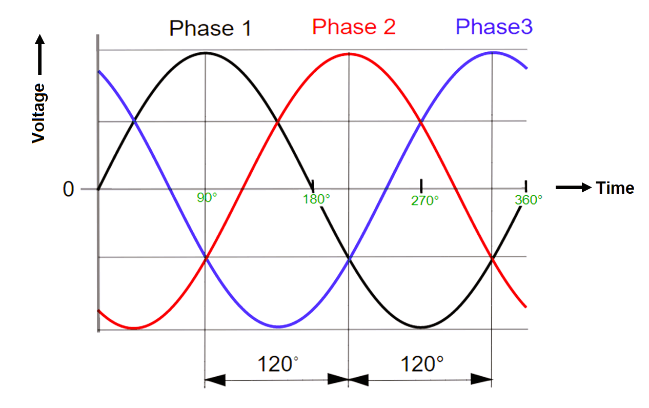
At the second stage, phase 2 leads in a positive form while the other two are in a negative phase.

At the third stage, phase 3 leads in a positive form while the other two are in a negative phase. This is a very good result as compared to single-phase supply; where a leading-edge comes after a long interval.

The voltage supplied between phase and neutral is 230V and the voltage between two phases is 440V. It is found that due to a good amount of positive edges in regular intervals, constant power is supplied to the load. This shows that a three-phase system will supply more output power.

Single Phase versus Three Phase Power

Due to low power output from single-phase supply, it is more used for domestic purposes like residential homes and offices. A normal power socket that you use at home for charging your mobile or turning on your TV is a 230V supply.

Due to the high output from the three-phase supply, it is more used in industrial applications and other heavy-duty processes which draw a large amount of current for driving their loads. It is to be noted that raw power from distribution grids is a three-phase supply; it is distributed to your homes for single-phase use through normal distribution boards.

The design, handling, and maintenance of a single-phase power supply are easier as compared to a three-phase supply.

The torque handling capacity and current carrying capacity are larger in a three-phase supply system than in a single-phase supply system.

The efficiency of a three-phase system is higher than a single-phase system.

Single-phase supply is ideal for small loads like lighting, heating, cooling, fan system, etc., whereas a three-phase supply is ideal for larger loads like heavy motors.

The neutral wire is compulsory in single-phase supply; otherwise, it cannot function. But, the neutral wire is optional in three-phase supplies. It can be found that the delta connection has no neutral wire, but a star connection may or may not have a neutral wire.

A big lagging in single-phase supply is that if the phase wire fails, then the system will break down. But, in a three-phase supply, even if one phase fails, the remaining two can be used to supply power.

If you liked this article, then please subscribe to our YouTube Channel for Electrical, Electronics, Instrumentation, PLC, and SCADA video tutorials.

You can also follow us on Facebook and Twitter to receive daily updates.

Read Next:

  • What is a VFD?
  • UPS Working Principle
  • Stop Switch Spurious Trip
  • Motor Control Timer Circuit
  • Compare Alternator & Generator
Don't Miss Our Updates
Be the first to get exclusive content straight to your email.
We promise not to spam you. You can unsubscribe at any time.
Invalid email address
You've successfully subscribed !

Continue Reading

What is a Buchholz Relay? Working Principle
What is an Inductor? – Types of Inductors
Motor Control Circuit Wiring
Difference Between HV and LV Cables
Types of Industrial Storage Batteries
Motor Maintenance, Troubles, Regular Checks, Performance
Share This Article
Facebook Whatsapp Whatsapp LinkedIn Copy Link
Share
Leave a Comment

Leave a Reply Cancel reply

Your email address will not be published. Required fields are marked *

Stay Connected

128.3kFollowersLike
69.1kFollowersFollow
210kSubscribersSubscribe
38kFollowersFollow

Categories

Explore More

Motor Control Signal Interface
How to Check the Continuity of Protective Conductors?
Motor Protection Circuits
How Do Air Compressor Filters Clean and Protect the System?
Difference Between NEMA and IEC Motors?
Electrical Earthing Calculations
Motor VFD Drive features
Stepper Motor Working Principle

Keep Learning

What is Electrical Interlocking?

Electrical Contactor Interlocking Circuit Explained

Alternating Current

Difference between AC and DC

Motor STAR - DELTA Working principle

Motor STAR – DELTA Starter Working Principle

Advantages of Star and Delta Systems

Advantages of Star and Delta Systems

Motor Control On-Delay Timers Circuit

Motor Control Timer Circuit – Automatic Motor START and STOP

Difference Between AIS and GIS Panels

Difference Between AIS and GIS Panels

Wave Trap in Power Line carrier Communication

What is a Wave Trap? – Power Line Carrier Communication

Volume Damper

What is a Damper? Types of Dampers in HVAC

Learn More

Allen-Bradley VFD

Why V/f Ratio is kept Constant in VFD?

What is Swing Check Valve ?

GSD File installation in Simatic Manager

How to Install GSD File in Step 7 PLC using Simatic Manager?

Latest Control Valves Interview Questions

Control Valve Interview Questions and Answers

Analytical Measurement Multiple Choice Questions

Analytical Measurement Multiple Choice Questions

flow-meter-accuracy-calculation

Impact of Flow Meter Accuracy

Difference between Force and Power

Difference between Force and Power

Magnetostrictive Transducers Objective Questions

Magnetostrictive Transducers Objective Questions

Menu

  • About
  • Privacy Policy
  • Copyright

Quick Links

  • Learn PLC
  • Helping Hand
  • Part Time Job

YouTube Subscribe

Follow US
All rights reserved. Reproduction in whole or in part without written permission is prohibited.
Welcome Back!

Sign in to your account

Username or Email Address
Password

Lost your password?