In essence a valve simply functions as a restriction in a flow line, with flow areas A1 and A2 and pressure differential p1 – p2, as shown in Below Figure.
Valve Characteristics

The below mentioned flow equation describe the flow rate of a fluid through a valve. The form of this equation used by valve suppliers is:

where C is the valve flow coefficient, q the flow rate of the liquid through the valve, Δp = p1 – p2 the pressure difference across the valve and G the specific gravity (relative density) of the fluid.
For historical reasons, the flow rate q, in above Equation, is measured in gallons per minute (gpm) and the pressure difference Δp, in pounds per square inch (psi). Valve coefficient, C is fundamentally determined by the effective flow areas A1 and A2 of the valve.
The value of C will therefore change from zero (when the valve is fully closed) to a maximum value (when the valve is fully opened).
Assume that a valve is opened a certain amount x (with x denoting the fractional valve opening or valve travel between 0 and 1 ( 0% to 100%)).
The flow rate q, of the liquid (we will assume water with G = 1 ), flowing through the valve, is now allowed to increase until the pressure Δp across the valve, reaches a maximum of say 4 psi (assumption).
We may conceivably expect the results depicted in Below Figure, shown for x = 0 (valve fully closed), x = 0.25 (valve one quarter open), x = 0.5 (valve half open), x = 0.75 (valve three quarters open) and x = 1 (valve fully open).

The special value of C that corresponds to the valve fully open, is called the characteristic flow coefficient of the valve and denoted by CV.
The characteristic flow coefficient CV, is an extremely important parameter of a specific valve, and is used extensively when choosing the correct valve for a certain application.
For the valve characteristics in Above Figure, for example, CV = 40.
The way q varies when the pressure is kept constant (normally the rated pressure drop across the valve for maximum flow) and the way C changes as the valve opening x changes, may be available for a particular valve, provided by the manufacturer in tabulated format.
For example, the graph of q (with Δp = 4 psi) as a function of x and the graph of C as a function of x, are shown in Below Figures (a) and (b) respectively, for the flow characteristics of our hypothetical valve, depicted in above Figure.

The different values of C obtained as the valve travels through its full range (or stroke as it is also called) from closed to open, is generally expressed in the following format, by valve manufacturers:
C = CV×f(x) …Equation 1
where f(x) is called the inherent valve characteristic of a particular valve. For example, from the graph of C, in Above Figure (b), we could express C as:
C = 40x
and we conclude therefore from Equation 1, that CV = 40 and f(x) = x.
The function f(x) varies from 0 (valve closed with x equal to 0) to 1 (valve fully open with x equal to 1). The inherent valve characteristic f(x), is intimately linked to the flow rate q through a valve, as we can see if we replace C with CVf(x) (as per Equation 1), to rewrite the valve Equation in the form:

It is indeed clear from above Equation that if we keep Δp constant (for a given liquid, G is constant as well), q and f(x) will have exactly the same shape.
A valve for which f(x) = x, is called a linear valve because the flow rate will change linearly with valve opening x. Depending however on the valve design, f(x) may also reflect quick opening or equal percentage (slow opening) characteristics, as shown in Below Figure.
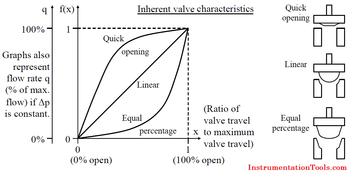
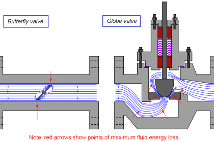
The flow behaviour of a valve is dictated by the manner in which the flow areas A1 and A2 changes with valve position and therefore by the style and design of the valve trimming and in particular the design of the valve seat and closure member (plug).
The quick opening flow characteristic provides for maximum change in flow rate at low valve travels with a nearly linear relationship. Additional increases in valve travel gives sharply reduced changes in flow rate.
The linear flow characteristic curve allows the flow rate to be directly proportional to the valve travel (Δq/Δx equals a constant) or in terms of the inherent valve characteristic, f(x) = x.
An equal percentage valve starts initially with a slow increase in flow rate with valve position which dramatically increases as the valve opens more.
The term equal percentage for a slow opening characteristic curve may at first be confused with the description of a linear characteristic curve.
However, for an equal percentage valve, Δq/Δx at any stage, is proportional to the flow rate q at that moment. This is in contrast with a linear characteristic for which Δq/Δx is constant.
That Δq/Δx is proportional to q, may be rephrased as Δq/q is proportional to Δx. This means the percentage change Δq with respect to the current flow rate q (that is (Δq/q)×100), is equal at every valve travel position x for the same change in valve travel Δx, hence the term ‘equal percentage’.
The inherent valve characteristic for an equal percentage valve is exponential in nature and is normally given by valve manufacturers in the form
![]()
where R is a constant for the valve.
The exponential behaviour of an equal percentage valve is explored further in Below Example
An equal percentage valve delivers 8 gpm of water when the valve is 50% open (x=0.5). When the valve is 60% open (x=0.6), the flow rate increases to 16 gpm. Estimate the flow rate through the valve when it is 70% open (x=0.7).
Assume that the pressure drop across the valve remains constant.

Answer:
When the valve opens from 50% to 60%, the flow rate changes from 8 gpm to 16 gpm. This means that Δq is 8 gpm. when Δx is 0.1 and q = 8.
Therefore Δq/q = 8/8 = 1 and the percentage change is 100% (Δq/q×100) at x = 0,5.
For an equal percentage valve, the percentage change in flow rate when the valve opens from 50% to 60%, (Δx = 0.1) must be equal to the percentage change in flow rate when the valve opens from 60% to 70% (the same Δx of 0.1).
Therefore Δq/q at x = 0.6 must also be 1 (or 100%) for Δx = 0,1. But q is 16 gpm. when the valve is 60% open and we conclude that Δq should be 16 gpm. when the valve opening changes from 60% to 70%.
The flow rate through the valve is therefore approximately 32 gpm. at 70% valve opening.
Installed flow characteristic
When valves are installed with pumps, piping and fittings, and other process equipment, the pressure drop across the valve will vary as the valve travel changes.
When the actual flow in a system is plotted against valve opening, the curve is called the installed flow characteristic and it will differ from the inherent valve characteristic which assumed constant pressure drop across the valve.
When in service, a linear valve will in general resemble a quick opening valve while an equal percentage valve will in general resemble a linear valve.
Typical application of quick opening, linear and equal percentage valves
i) Quick opening valve
- Frequent on-off service.
- Used for systems where ‘instant’ large flow is needed (safety or cooling water systems).
ii) Linear valve
- Liquid level and flow control loops.
- Used in systems where the pressure drop across the valve is expected to remain fairly constant.
iii) Equal percentage valve (most commonly used valve)
- Temperature and pressure control loops.
- Used in systems where large changes in pressure drop across the valve are expected.


Provided Excellent control valves knowledge with graphics, equation,
what is your refrence article or manual or documents for your equation mentioned ?
Dear Sir,
Wonderful explanation.
I have one question about Cv mentioned on tag plate of Control Valve. As per above explanation, Cv indicates flow(Obviously max) through 100 % opened control valve having DP equal to 1(unit).
1) How this Cv can be interpreted for any intermediate position of valve?.
2) is it necessary to have DP across valve = to 1(unit) during normal operation?
Thanking You.
Great
Good article
I am sorry that I cannot participate in the discussion now. I don’t have the information I need. But this topic interests me very much.