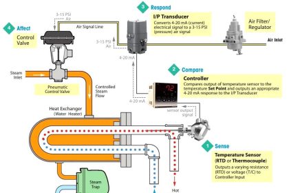
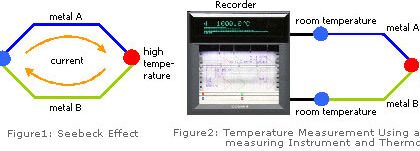
Temperature sensors fall into two general categories: thermocouples (TCs) and resistance temperature detectors (RTDs).
There are many resources discussing the selection process, so for this discussion, we will concentrate on how these behave in operation, as well as what can go wrong with each.
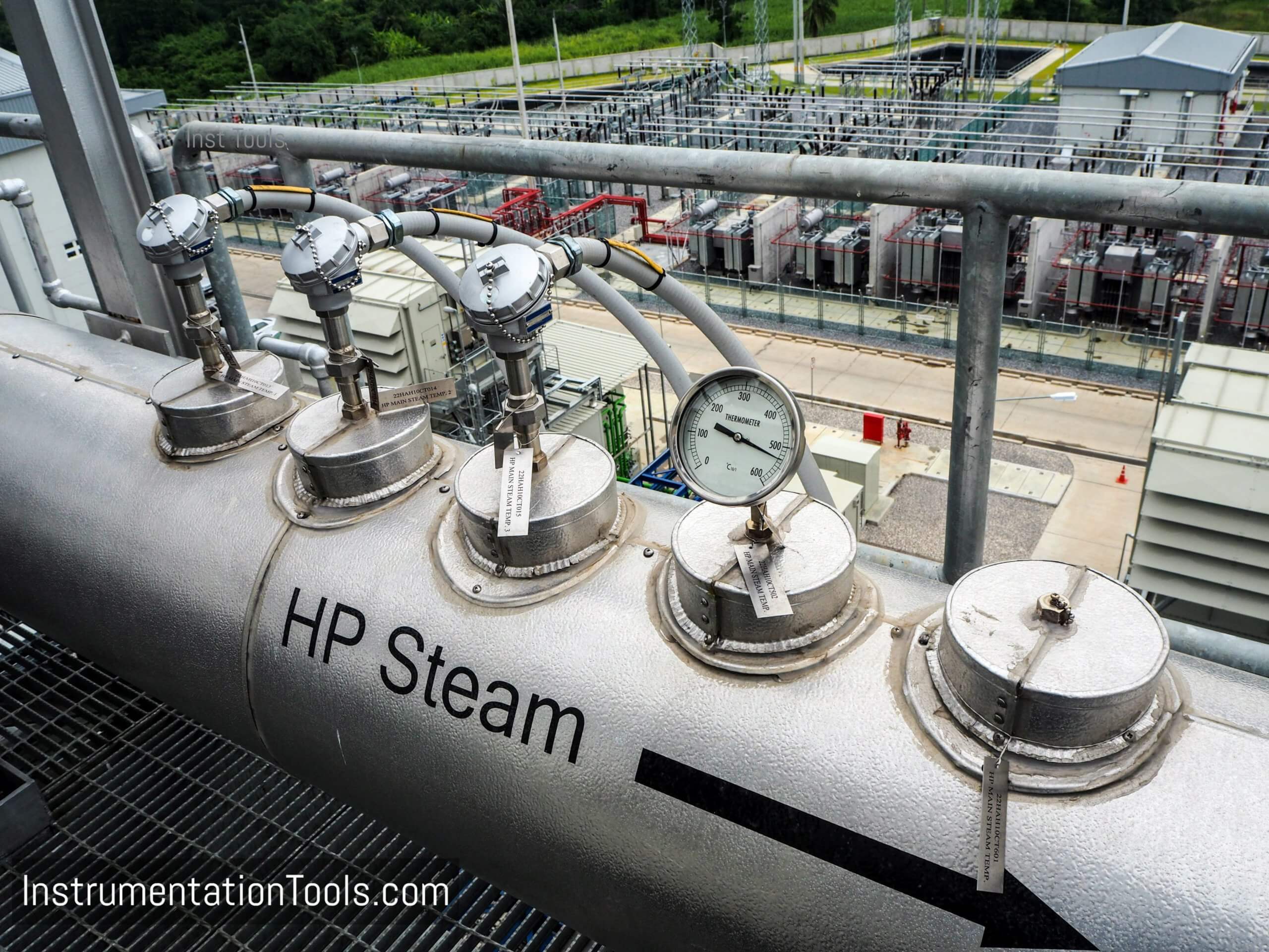
Sensor elements are typically enclosed in a stainless-steel sheath, which is then inserted into a thermowell.
Some sensor and thermowell combinations are paired as matched sets, designed to fit precisely for best heat transfer and high accuracy.
Other approaches use piece-part components, and it is up to the installer to match them closely.
Some users prefer to wire each TC or RTD directly to the host system input, but this complicates the installation and can impair performance.
For example:
- The thermocouple cabling from the sensor to the input card must match the sensor. If a different type of sensor needs to be installed, the cabling must be changed.
- Likewise, the input card must match the sensor, although some input cards allow for multiple options.
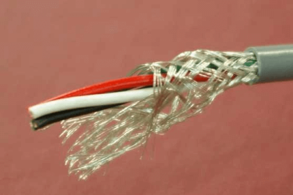
- The weak signals from a TC or RTD cannot be sent over long distances and are subject to problems caused by electrical interference.
Adding a temperature transmitter close to the sensor eliminates all these problems:
- A 4–20 mA with HART or digital protocol such as FOUNDATION Fieldbus, provides a much more robust signal that can be sent longer distances.
- There is no need for special cabling nor a special input card.
- Most transmitters work with a variety of RTD and thermocouple types, making it easy to change the sensor when required.
- Multiplex transmitters can capture data for multiple sensors and send it back on one cable.
- Smart transmitters can collect and send diagnostic, calibration, and other data.
- WirelessHART transmitters are also an option, eliminating wiring and the need for control system inputs, which may be in short supply. These smart transmitters have built-in power modules and can run for years without any required maintenance.
While these capabilities are all helpful, the most important advance in many applications is the transmitter’s intelligence: the ability to turn the sensor and transmitter combination into a smart instrument able to send diagnostic information to the host system.
Temperature sensors exhibit tell-tale signs when they are suffering from mechanical deterioration, or from wiring and termination problems.
These can be spotted by the transmitter and used to call attention to incipient problems before they escalate to a failure.
Many temperature measurement applications suffer from electrical noise, spiking, and signal dropouts.
Noise can come from electromagnetic interference, often caused by radios, motors, and lightning.
Other problems can be caused by wiring problems, mechanical shock, or vibration. These can be detected, diagnosed, and possibly even corrected by sophisticated transmitters.
Even with close coupling between sensor and transmitter, noise or dropouts can still be problematic, so most users apply damping to suppress the effects.
While damping improves stability, it increases response time during rapid changes in process temperature.
A better approach is to use the signal validation capabilities built into the transmitter as part of its signal processing and diagnostic functions.
Thermal inertia of a temperature sensor inside a thermowell makes measuring extremely fast temperature changes ( i.e. 200 °C to 400 °C) in half a second, physically impossible.
Even if the transmitter sees such an instantaneous shift between successive readings, it can reasonably assume the change is a spike (or dropout if the change is negative), and simply repeat the last good measurement.
This approach provides stability without damping or slow response, preventing the overall system from being disrupted unnecessarily, but it should not be applied where the measurement can legitimately see fast full-scale excursions.
Although a sensor can be damaged by an extreme mechanical shock event, most failures are caused by ongoing vibration, loose terminations, corroding connections, or chemical attack.
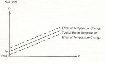
These can weaken the sensor and wiring, causing the number of spikes and dropouts to increase over time. These can also cause the sensor to drift, decreasing accuracy over time.
The transmitter can detect and trend this increasing number of problems to predict impending failure, alerting maintenance early enough to prevent total signal loss.
Signal validation digs deeper into the condition of the sensor itself, which can improve both the safety and reliability of temperature measurements.
When fast response times or high temperatures (>600 °C) are involved, and when a high degree of precision is not required, TCs are often preferred over RTDs.
TCs are typically more physically robust than RTDs, but they can fail in a way not readily apparent.
The junction at the tip where the dissimilar wires are joined is the temperature measuring point, but if physical shock or vibration breaks down the insulation and the two wires form a contact somewhere else, this new contact point becomes the temperature measuring point, wherever it might be.
Since this new junction is invariably farther from the hot process, in most hydrocarbon applications a damaged TC will read low, although the opposite is true in cryogenic applications.
Most processes are dangerous when they run too hot, so a low reading can create a safety risk.
Modern smart temperature transmitters are configurable to accept either RTD or TC inputs. When configured for a TC, the transmitter uses its voltage circuitry to determine temperature.
But the transmitter can also use its resistance measuring circuitry, which would be used with an RTD, to monitor the resistance of the TC.
While the resistance of the TC cannot be used to determine temperature, it does help detect and predict failures.
Changes in TC circuit resistance can suggest several things. If the resistance goes to infinity, the circuit is open. If the resistance decreases from its normal level, there may be a short. If resistance increases, the wire or termination may be corroding.
These changes may be immediate, but more often they are gradual, so measuring and trending resistance changes and analyzing the results can be used to predict failure and improve reliability.
When a temperature measurement is especially critical to a process, redundant sensors can be an option.
Temperature sensors are relatively inexpensive, and some transmitters have the ability to accept and process signals from multiple sensors. If the measurements from the two sensors differ by an amount programmed into the transmitter, it can alert operators to a problem.
Similarly, if one sensor fails, an automated backup switchover allows the transmitter to switch immediately from the primary to a backup sensor, reducing the chance of losing a temperature reading. This Hot feature can be used with dual-element sensors or two independent sensors.


Hello,
I’m very interested on the technology of this smart transmitter and want to have a deep discussion with the company who produce it in order to see if it can answer my requirements in my production. could you please share with me the contact info of such company?