Inst ToolsInst ToolsInst Tools
  • Courses
  • Automation
    • PLC
    • Control System
    • Safety System
    • Communication
    • Fire & Gas System
  • Instrumentation
    • Design
    • Pressure
    • Temperature
    • Flow
    • Level
    • Vibration
    • Analyzer
    • Control Valve
    • Switch
    • Calibration
    • Erection & Commissioning
  • Interview
    • Instrumentation
    • Electrical
    • Electronics
    • Practical
  • Q&A
    • Instrumentation
    • Control System
    • Electrical
    • Electronics
    • Analog Electronics
    • Digital Electronics
    • Power Electronics
    • Microprocessor
  • Request
Search
  • Books
  • Software
  • Projects
  • Process
  • Tools
  • Basics
  • Formula
  • Power Plant
  • Root Cause Analysis
  • Electrical Basics
  • Animation
  • Standards
  • 4-20 mA Course
  • Siemens PLC Course
Reading: Label the Electrical Circuit Schematic
Share
Notification Show More
Font ResizerAa
Inst ToolsInst Tools
Font ResizerAa
  • Courses
  • Design
  • PLC
  • Interview
  • Control System
Search
  • Courses
  • Automation
    • PLC
    • Control System
    • Safety System
    • Communication
    • Fire & Gas System
  • Instrumentation
    • Design
    • Pressure
    • Temperature
    • Flow
    • Level
    • Vibration
    • Analyzer
    • Control Valve
    • Switch
    • Calibration
    • Erection & Commissioning
  • Interview
    • Instrumentation
    • Electrical
    • Electronics
    • Practical
  • Q&A
    • Instrumentation
    • Control System
    • Electrical
    • Electronics
    • Analog Electronics
    • Digital Electronics
    • Power Electronics
    • Microprocessor
  • Request
Follow US
All rights reserved. Reproduction in whole or in part without written permission is prohibited.
Inst Tools > Blog > Animation > Label the Electrical Circuit Schematic

Label the Electrical Circuit Schematic

Last updated: March 4, 2021 11:26 am
Editorial Staff
Animation Control Systems PLC Tutorials
No Comments
Share
1 Min Read
SHARE

Here we give you the basic full-wave bridge rectifier to identify the electronic components in the circuit. Next, you have to identify the labels in the electrical circuit schematic.

Contents
Electrical Circuit Label SchematicSTART

Drag the letter that corresponds with the schematic label, drop it into the colored circle next to the correct symbol.

Electrical Circuit Label Schematic
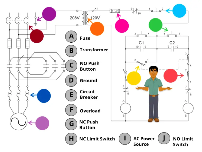
Electrical Circuit Label Schematic Quiz

You have to drag and drop the correct technical words to the respective circle.

Requirements: Desktop or Laptop

Click on the below start button to launch the schematic.

START

Also Check: Online Simulations

If you liked this article, then please subscribe to our YouTube Channel for PLC and SCADA video tutorials.

You can also follow us on Facebook and Twitter to receive daily updates.
Don't Miss Our Updates
Be the first to get exclusive content straight to your email.
We promise not to spam you. You can unsubscribe at any time.
Invalid email address
You've successfully subscribed !

Continue Reading

Flexible Input Output Modules
Network Switch Port Allocation Details
DCS Troubleshooting Control Valve Loop
PLC vs PAC – Understanding the Key Differences and Similarities
Equivalent Logic Gates using PLC Ladder Diagrams
What are User Defined Function Blocks in PLC?
Share This Article
Facebook Whatsapp Whatsapp LinkedIn Copy Link
Share
Leave a Comment

Leave a Reply Cancel reply

Your email address will not be published. Required fields are marked *

Stay Connected

128.3kFollowersLike
69.1kFollowersFollow
210kSubscribersSubscribe
38kFollowersFollow

Categories

Explore More

CX-Programmer Products Sorting & Counting – Omron PLC
Self-regulating Processes – Liquid Flow Control
PLC Programming Example on Bottle Line Control
Testing and Validation in PLC Development
Types of Digital Outputs in PLC
Liquid Level Control using Flow Loop
What is Complementary Split Range Control (CSRC)?
Scale and Normalize Instructions in PLC

Keep Learning

Steam Turbine Interlocks

What are the Interlocks for Steam Turbine?

Overview of Industrial Control Systems

Overview of Industrial Control Systems

Design a PLC program for Operational Sequence of Packaging Process

Design a PLC program for Operational Sequence of Packaging Process

Basic PLC Exercise on Heater and Cooler for Students

Basic PLC Exercise on Heater and Cooler for Students

Use of Regions in SCL Language

Use of Regions in SCL Language

PLC Program for an Alternate output circuit

PLC Program for Alternate Output Circuit with Latched Function

Argonite Fire Suppression System Animation

Argonite Fire Suppression System Working Principle

PID Controller Responses to Two momentary step inputs

PID Controller Response with different Input Signals

Learn More

Wattmeter Principle

Wattmeter

PLC Timer Programming Examples – TON, TOF, TP and TONR

Scaling in PLC

How to do Scaling for Analog Input in RSLogix 500?

vibration probe mounting

Mechanical Vibration Switch Principle

LVDT-Operation-Principle-Animation

LVDT Working Principle Animation

Fieldbus Segment

Basics of Foundation Fieldbus

Control Valve End Connection

Control Valve End Connection

Types of Circuit Breakers

Types of Circuit Breakers, Advantages, Disadvantages

Menu

  • About
  • Privacy Policy
  • Copyright

Quick Links

  • Learn PLC
  • Helping Hand
  • Part Time Job

YouTube Subscribe

Follow US
All rights reserved. Reproduction in whole or in part without written permission is prohibited.
Welcome Back!

Sign in to your account

Username or Email Address
Password

Lost your password?