In this article, we shall learn about the Instrument protection method, steam tracing.
The need for housings, heating, and insulating instruments and impulse lines will depend on the environmental conditions like considering winters in the locality.
To ensure that the instruments remain operable under the most severe conditions, the design should be based on the lowest temperature and highest wind velocity for the coldest month of the year. Where applicable, the use of either steam or electrically heat-traced tubing bundles can simplify installation and reduce future maintenance problems.
In designing a heating system, it is usually necessary to consider instruments in the following four general categories.
Category 1:
Instruments for measuring and controlling process streams that have to pour points below 32°F such as gases, light hydrocarbons, and intermediate distillates.
Although some of these streams, when wet, form hydrates that solidify above 32°F, it is usually sufficient merely to warm such systems to prevent the formation of ice. Therefore, such installations are designated warming services.
Category 2:
Instruments for measuring and controlling streams with elevated pour points, such as pitch, heavy residuals, and process chemicals such as phenol that solidify above 32°F.
In such systems, it is necessary to keep the temperature of the process fluid above its pour point to ensure free flow. Such installations are designated high-pour-point services.
Category 3:
Special instrumentation and piping systems, which often require additional protection for operation and maintenance tailored to the service involved.
Process stream analyzers and their sampling systems are an example.
Category 4:
Instruments with specific temperature limitations, both maximum and minimum, imposed by the manufacturer to ensure accurate and reliable operation.
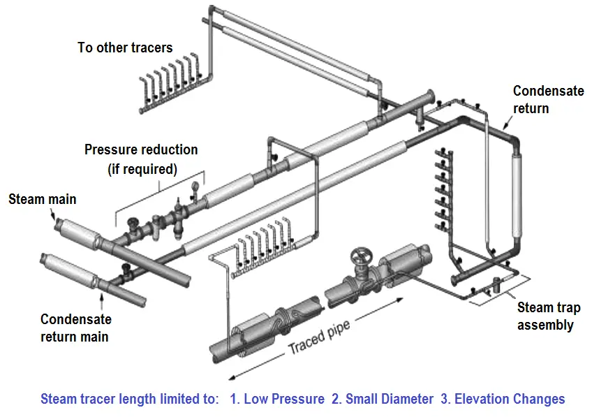
Steam Tracing
Steam tracing should be used when it is the practical choice for the plant or specific units of the plant and when it is possible for the contents of the pipes, equipment, or instruments to freeze, condense, crystallize, separate or become too viscous to pump under local temperature conditions.
Since steam is normally available in refinery process units, steam heating has the advantage of being readily accessible. Steam supplies high-density heat from condensation and large quantities of heat can be obtained from a single tracer line. On the other hand, steam delivers heat at a temperature that corresponds to the saturated steam pressure in the tracer, a minimum of 212°F (10O°C), which may overheat some instruments or impulse lines unless care is exercised.
Warming services require steam tracing to prevent the formation of ice and hydrates and undesirable gas condensation. The problem, however, is to avoid overheating, which can cause boiling in the instrument and lines or which can cause damage. Danger from overheating can be minimized by “light tracing,” in which direct contact between the hot tracer and the line or instrument is prevented by the use of insulation or spacing.
The entire tracing system for impulse lines should be carefully insulated and waterproofed. Particular care should be used at the point of measurement and at the entry into the insulated enclosure. A durable protective cover should be used. Where stainless steel tubing is used, chloride-free insulation must be specified to prevent stress corrosion cracking.
The system should be designed and installed to minimize damage to the insulation during routine service or maintenance. Commercially available insulating enclosures designed to allow for routine maintenance can be used.
Copper or stainless-steel tubing sized for the particular service should be used to carry the heating steam. Aluminum tubing should not be used because it is subject to corrosion, particularly by magnesia insulation. Carbon steel tubing rusts not only externally but internally when heating is seasonal or intermittent. The internal rust clogs or damages traps.
Joints in tracing tubing should be avoided if possible. When joints are necessary, they should be made outside the insulation with expansion loops to prevent stress on the fittings. Only high-quality fittings should be used. To protect personnel, the loops should be separately insulated.
The entire tracing system for impulse lines should be carefully insulated and waterproofed. Particular care should be used at the point of measurement and at the entry into the insulated enclosure. A durable protective cover should be used. Where stainless steel tubing is used, chloride-free insulation must be specified to prevent stress corrosion cracking.
The system should be designed and installed to minimize damage to the insulation during routine service or maintenance. Commercially available insulating enclosures designed to allow for routine maintenance can be used.
The difference between warming service and high-pourpoint service is the temperature required to keep the material fluid in the instrument and impulse lines. When low-pressure [less than 50 pounds per square inch absolute (350 kilopascals)] steam heat is used for high-pour-point service, heavy tracing is required.
More heat transfer can be achieved by using heat transfer cement or more than one tracer. As a general precaution, care must be taken to ensure that the high-temperature limit of the instruments and the temperature/pressure rating of the tubing are not exceeded.
Housings for instruments in high-pour-point service are usually identical to those used for instruments in warming service, except that a larger coil is required and extra protection may be necessary to prevent maintenance personnel from being burned.
Interest to add any further points? Share with us through below comments section.
Author: Kalpit Patel
Read Next:
- Electrical Ground Loops
- Purging of Instruments
- Purged Impulse Lines
- Impulse Steam Traps
- Impulse Piping Installation


Would you please clarify the steam tracing is the responsibility of which department, instrumentation or mechanical piping engineering,
Thanks and best regards.