What are Loop Powered Devices?
A lot of loop setups will utilize an external power supply in order to power the devices which are attached to the current loop. It is possible, however, to power all the instruments on the loop with the power supplied for the loop itself. These devices are referred to as loop-powered. This particular setup can be used in situations where it is not practical to supply separate power to all of the devices or in hazardous areas where a low power solution is required. Working in an industry that requires process control, it is imperative to understand whether implementing a loop-powered solution is appropriate or not for your setup.
A fundamental principle of electricity is that current is the same at all points in a closed current loop. This is why the 4-20 mA current loop is the ideal analog standard for transmitting information over long distances, and through multiple meters, transmitters, data loggers, and other 4-20 mA loop devices. The current will be identical at all devices in the loop. As long as there is sufficient voltage, a 4 mA signal generated at the transmitter will still be a 4 mA signal when it reaches the receiver. This fundamental factor allows as many devices as the power supply can support to be powered by the current loop without affecting the process signal.
A loop-powered device is simply a process control device, such as a digital display, that takes advantage of this principle to power itself off of the 4-20 mA loop without affecting the current levels in that loop. Loop-powered instruments by their nature need to consume very little power in order to be able to operate with the finite power supplied to the loop. Consequently this fact defines the features found in loop-powered devices and their applications.
Loop Power Devices Characteristics
Loop-powered devices come with two input connections: a positive (+) and a negative (-). The current signal enters through the positive (+) terminal and leaves via the negative (-) terminal. Therefore the term ‘loop-powered’ is synonymous with the term ‘2 wire’ (meaning that only 2 connections/wires are involved in any of the connections between the transmitter, the power source and the output device).
In addition to being easy to wire and requiring very little power, there are a few other defining characteristics of loop-powered devices.
They typically do not feature LED displays nor mechanical relays. Process outputs and serial communications capabilities are quite limited. Loop powered devices, however, are normally less expensive, easier to install and will often feature hazardous area approvals such as Intrinsically Safe (I.S.) and Non-incendive (N.I.). Explosion proof loop-powered devices are also common as they significantly simplify installation.
Advantages
There are a few advantages to utilizing the power supplied for the current loop to power your devices rather than incorporating an additional power supply into your system. First and foremost, it might not be feasible to supply additional power to your system if your application is in a remote area, for example. In this case, your transmitter might be powered by a battery, solar cell, or some other power source and the other devices in the system would derive their power from the transmitter. The expense of running additional lines may also make additional power other than just the 4-20 mA signal cost prohibitive.
Because there is only one power source for the entire system (often supplied by the transmitter which is outputting the 4-20 mA signal), loop-powered devices are also incredibly simple to setup.
Only two wires, the positive and negative connections to the current loop, are required. This is in contrast to three and four wire setups, which incorporate an external power supply into the mix. This makes installation complexity minimal. Loop-powered devices are often much lower cost than other process control devices with built-in high power electronics. This is simply because the expensive components that could be included in these devices such as power supplies, mechanical relays, or advanced digital or analog signal output components are omitted in order to limit the amount of power necessary to operate the device.
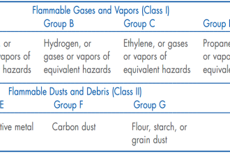
Many loop-powered devices are approved for use in hazardous areas as Non-incendive (N.I.) or Intrinsically Safe (I.S.). Both of these approvals require the device to consume such little power that it cannot cause combustion under normal operating or fault conditions, respectively. Since the power consumption of loop-powered devices is so low by necessity, they are usually easy candidates for these approvals.
Limitations
The advantages of utilizing loop-powered devices make them solid contenders for many process control applications. There are some drawbacks, however, which must be taken into account before planning to use loop power in your particular application. These drawbacks may be minor or could potentially completely disqualify the use of loop-powered devices.
First and foremost among the disadvantages is the fact that loop-powered devices are operating on the finite amount of power supplied to the 4-20 mA current loop, and add a voltage drop into the loop. The power supply for 4-20 mA loops is typically 24 V, but can vary. All of the loop-powered devices on the loop need to be powered by this one power supply. Because of this, it is imperative that you check the voltage drop specification on all of your devices in order to ensure that the power supply is capable of supplying enough voltage for all of the components within the loop. The sum of all the voltage drops on all devices in the loop must be less than the voltage of the power supply. It is best to allow some room for error and supply fluctuation, such that the total of all voltage drops is less than 80% of the supply voltage.
The voltage drop specification is supplied in a variety of formats. It could potentially be formatted as a maximum voltage drop for the device (e.g. 3.0 Vmax), a voltage level at a specific current level (e.g. 3V @ 20 mA), an input impedance (e.g. 150 Ω), or a lookup table showing supply voltage versus equivalent resistance.
Critical Specifications to Remember
If you are considering a loop-powered device for your application, there are several critical specifications you should be aware of before making your final choice:
- VOLTAGE DROP: Check the voltage drop specification to ensure the power supply delivers enough voltage for all of the components within the loop.
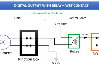
- OUTPUTS: If outputs are required from your loop powered device, carefully review the type of outputs and the ratings that are available. Loop-powered devices are required to have low-power outputs, such as passive 4-20 mA outputs rather than self-powered outputs, and open collector transistor outputs rather than relays. Be sure your system is designed to work with the outputs you have available. Plan in advance for any external power supplies, external relays, or other equipment your system may require to work with these outputs.
- OPERATING TEMP: This is a spec that is often overlooked. It is critical for devices with LCD indication, since many will have trouble in cold weather, such as -20 or -40°C
Summary
The term loop-powered simply means that the device in question receives its power from the 4-20 mA process signal connected to the device. This is possible because current is the same throughout the 4-20 mA loop, so voltage drops caused by loop-powered devices do not affect the current signal.
Loop-powered devices are simple, easy to wire and use very little power. However, it is important to be aware of the limitations of loop-powered devices, such as the unavailability of relays, LED displays, or advanced serial communications. You must be sure to pay attention to the specifications, such as voltage drop, output requirements, power requirements, operating temperature and hazardous area approvals, in order to avoid problems with your particular control system. If your application requires an inexpensive, easy-to install, low power solution and none of the aforementioned disqualifying factors apply, then loop power may be the right answer for your application.
Also Read: Basics of 4-20mA Loop


Good info
Thanks
Excellent information